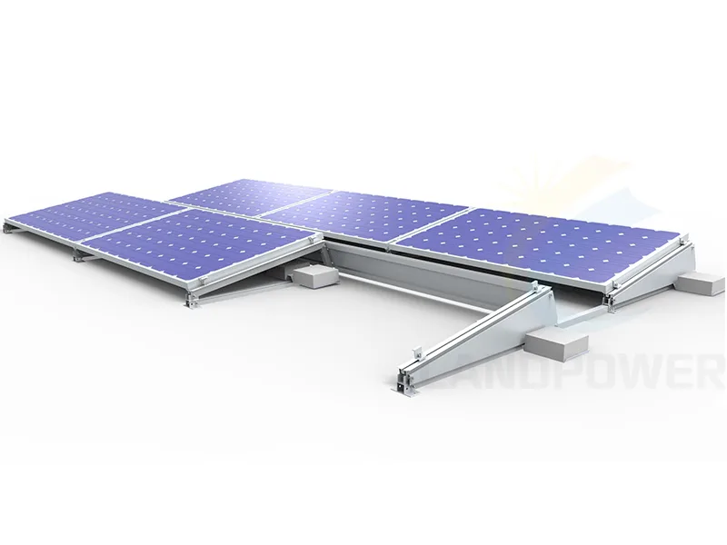
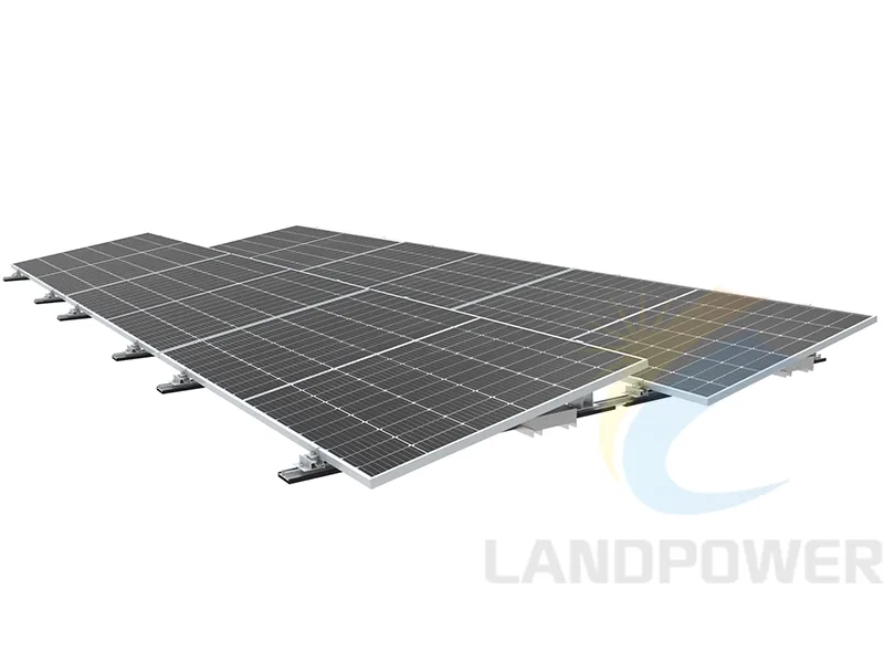
Flat Roof Mounting SystemBallasted Flat Roof Mounting Landscape
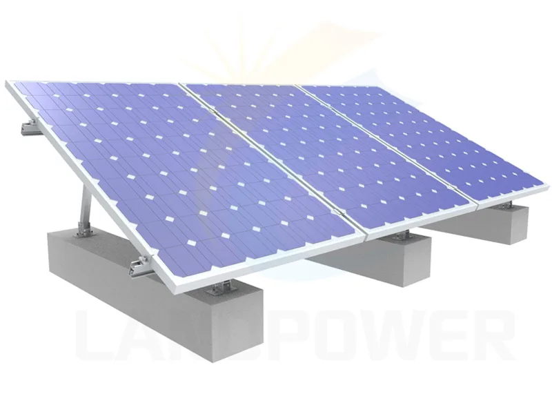
The Ballasted Flat Roof Mounting is design or solar panel panel installing in Landscape, Just few component,it is easy for installation,and they are cost-effective.
Open a product page for its available catalogue fields, then confirm the exact layout, item number, roof design basis, zoned ballast or attachment schedule, project BOM, documents and order terms in the RFQ.
Flat Roof Mounting SystemThe Ballasted Flat Roof Mounting is design or solar panel panel installing in Landscape, Just few component,it is easy for installation,and they are cost-effective.
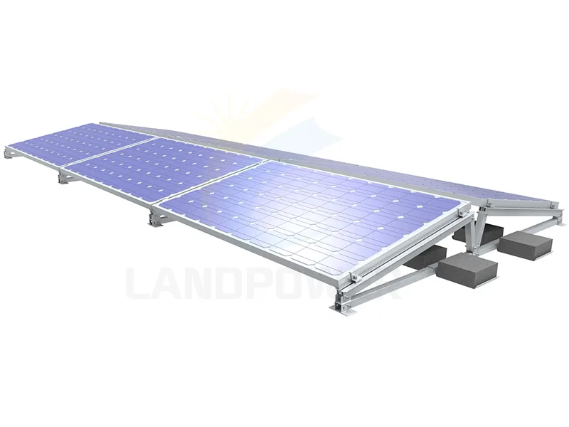
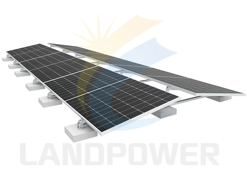
Flat Roof Mounting SystemThe East/West Ballasted flat roof mounting structure is simple and non penetrating solution for flat roof and low pitched roof,it is easy and quick mounting solution for achieving higher solar yields.
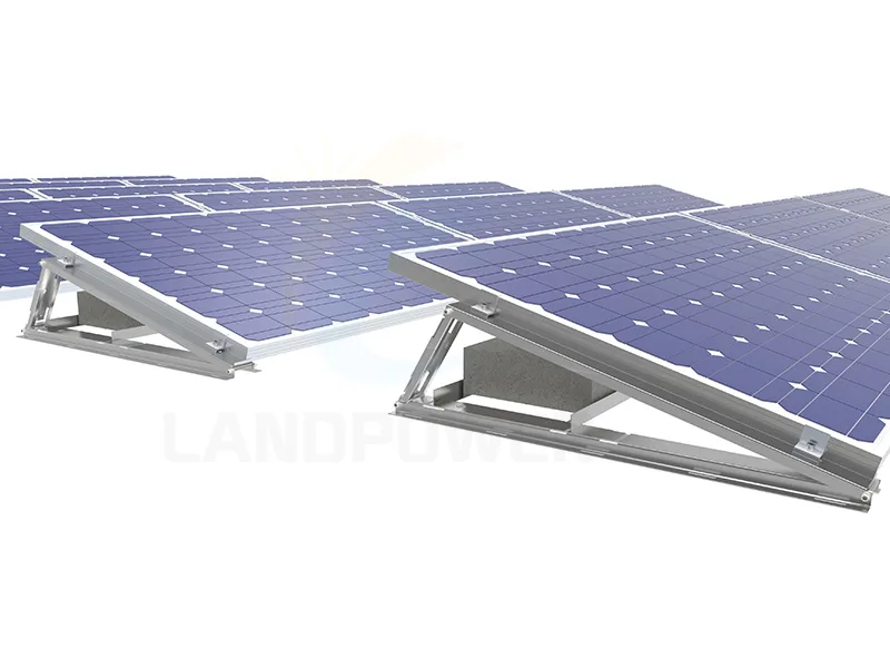
Flat Roof Mounting SystemThe Ballasted Flat Roof Mounting are easy solution to mount the panel,with anti-slide design,pre-assembled triangle,they are less components for easy to keep store.
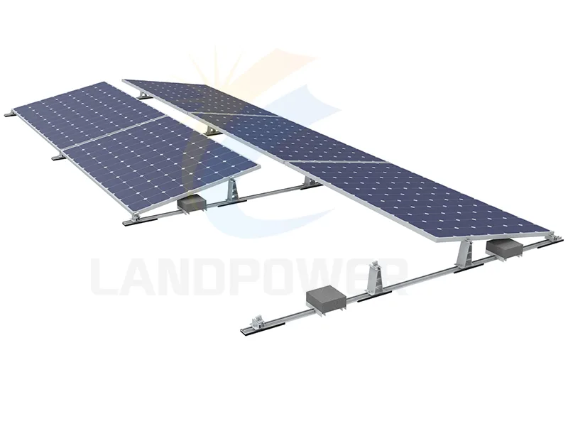
Flat Roof Mounting SystemThe Flat Roof Mounting is design for two row solar panel installation on flat roof,the are with triangle and mid clamp,end clamp etc,less components.Both for residential and commercial installation.
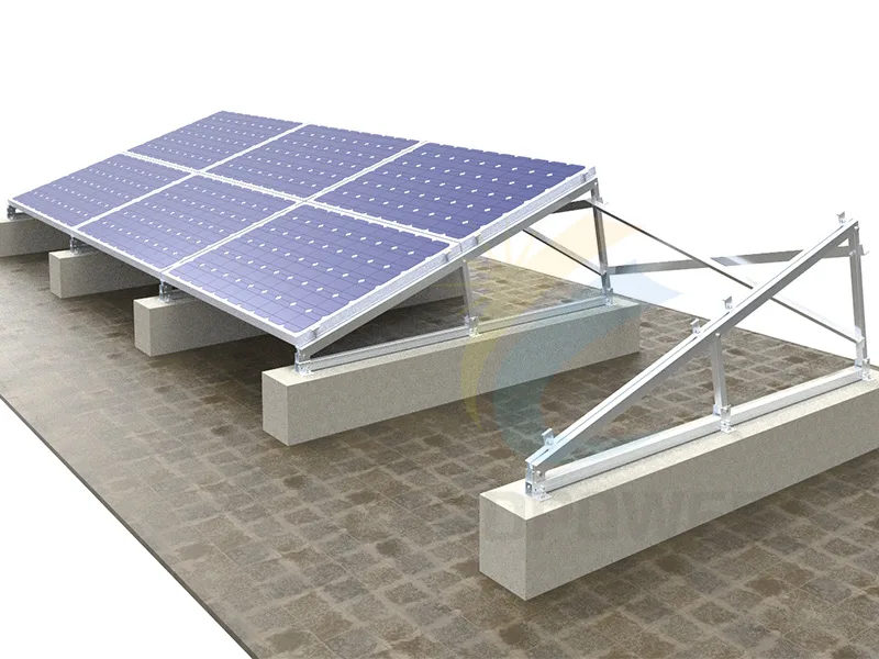
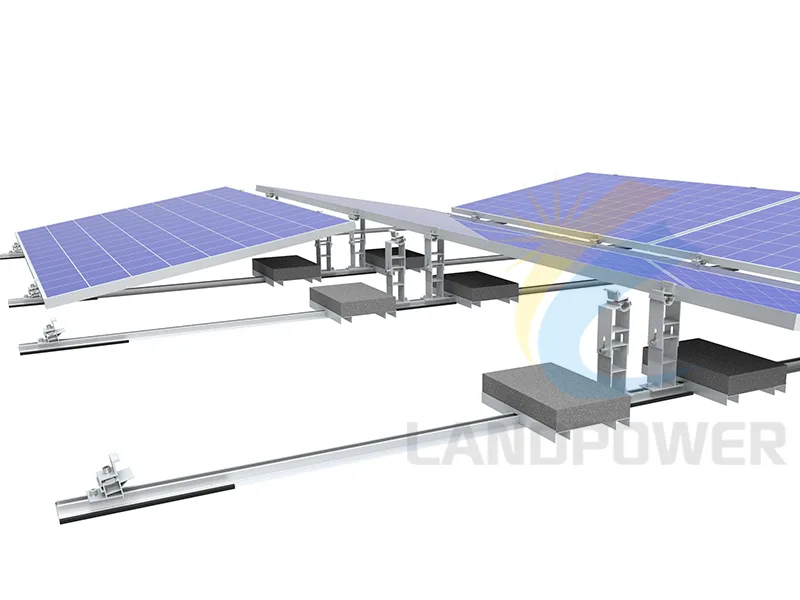
Flat Roof Mounting SystemFlat roof tilt up solar mounting are fast and easy mounting solution for flat roof,with few standardized items,and tilt angle adjustable,and competitive prices.
Flat Roof Mounting SystemThe New Flat Roof Ballasted Mounting are quick mounting solutions for both south facing and east west orientation, it easy and quick to use with less compoents.
Flat Roof Mounting SystemThe Flat Roof Ballast Solar Mounting Structure is for large solar panel and fixing point on the long side of solar panels, it is ideal for large solar panel.
Flat Roof Mounting SystemFlat Roof Ballasted Solar Panel Long Side Mounting is the ideal solution to mount big solar panel on flat roof or trapezoidal roof, it is simple, easy and strength mounting structure for large panel.
Flat Roof Mounting SystemUniversal flat roof solar mounting structure are best solution for large solar panel to fix in long side or short side of solar panel, few components, and easy to install and keep stock
Orientation and support layout affect row spacing, ballast distribution, wind exposure, roof loading, drainage, installation sequence and maintenance access.
Review front and rear supports, tilt, row spacing, ballast trays or blocks, module support points and edge-zone treatment against the approved aerodynamic or structural basis.
Back-to-back geometry can change roof coverage and row behavior. Confirm module orientation, shared supports, gaps, drainage, maintenance corridors, wind zones and ballast schedule.
Landscape, two-row and long-side layouts must stay within the exact module manufacturer's support and clamp guidance; similar module dimensions do not prove the same permitted support locations.
Confirm hinge and brace geometry, permitted tilt positions, locking method, module frame interface, service access and the site-specific effect of tilt on wind and load paths.
A quote-ready request connects the module table and ballast or attachment concept to the actual roof structure and building constraints.
Identify concrete, metal deck or other substrate, insulation, membrane type, roof age, slopes, drainage points, seams, warranty conditions and areas that cannot accept load or penetration.
Provide the structural review route and allowable dead, live and point loads; check ballast blocks, bearing pads and load spread rather than comparing system mass alone.
Provide site, code, building height, parapets, exposure, wind and snow criteria, edge and corner zones, tilt and array gaps for the responsible calculation.
State exact module dimensions, mass, frame and support guidance plus orientation, tilt, row length, spacing, setbacks, obstacles, access and service routes.
Confirm pad or separator compatibility, puncture and abrasion protection, water flow, ponding risk, roof penetrations, fire routes and roof-maintenance requirements.
Request the layout, zoned ballast or attachment schedule, calculations where included, component BOM, installation guidance, material records, packing plan and change-control process.

The approved solution must balance uplift resistance, roof capacity, membrane protection, drainage, movement and local building requirements for the actual configuration.
Ballast depends on roof zones, geometry, tilt, gaps, parapets, exposure, friction and the stated design method. A generic block count or catalogue mass should not be copied between sites.
Reserve capacity, point and distributed loads, deck and insulation behavior, ponding, penetrations and load paths require review by the responsible building and structural parties.
Wind-tunnel, test or calculation evidence only applies within its named product geometry, module size, array layout, roof assumptions, coefficients, safety factors and installation conditions.
Separator materials, abrasion, chemical compatibility, drainage, setbacks, access, fire pathways and roof-warranty conditions must be agreed for the building and jurisdiction.
Use the commercial rooftop solution for system context and the BOM guide to separate confirmed hardware from structural and roof decisions still awaiting approval.
Frame roof geometry, module layout, racking, electrical equipment, protection, delivery and local design responsibilities as one project scope.
Review solution context
Record module supports, ballast or attachments, accessories, quantities, drawings, evidence, exclusions and unresolved assumptions for comparable quotations.
Read the buyer guide
Use these answers to identify missing project inputs; final roof, structural, waterproofing, fire and installation approval remains with the responsible local parties.
No universal conclusion is safe. A project may use ballast, mechanical attachments or a hybrid approach depending on uplift, roof capacity, membrane and substrate, seismic or movement requirements, roof warranty and local rules. The approved project design decides the attachment strategy.
It is calculated from the selected system and array geometry, roof zones, building height, parapets, exposure, design wind and other loads, friction assumptions, module size, tilt, gaps, test or calculation basis and applicable code. The existing roof must also be checked for the resulting loads.
No. Verify module dimensions, mass, frame construction and the manufacturer's permitted clamp or support zones. Long-side, short-side, corner or other support arrangements need model-specific acceptance and compatible hardware.
Include roof drawings and build-up, membrane and substrate, roof condition and capacity, site and code, wind and snow criteria, parapets and zones, exact module, array layout and tilt, drainage and access, attachment restrictions, requested calculations and drawings, quantity, packing and delivery target.
Compare nine displayed flat-roof products across south-facing or single-slope, east-west, landscape, portrait, two-row and long-side ballast layouts. Product names help define a shortlist; they do not establish the permitted ballast, roof loading, wind performance or membrane compatibility. Confirm the roof build-up, reserve capacity, uplift design, attachment or ballast strategy, drainage, access, module interface, documents and complete project BOM.
Send the roof build-up and drawings, structural limits, module and layout, tilt, wind and snow basis, parapets and zones, membrane and drainage constraints, evidence scope, quantity, destination and delivery target.