
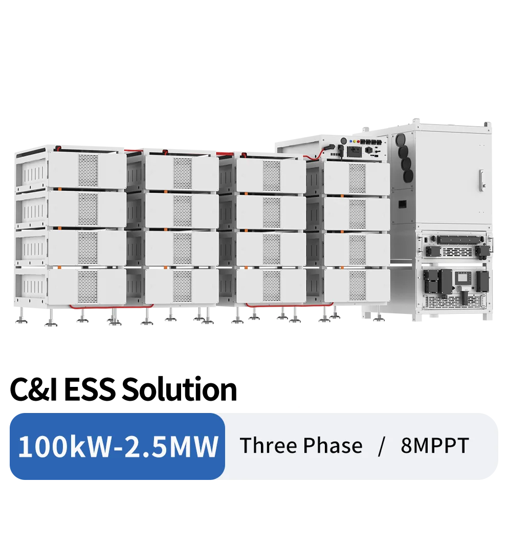
Compare the two displayed Deye modular C&I ESS solution pages
Open the exact architecture page for source-derived modules and claims, then confirm the released one-line, model revisions, cluster/PCS ratio, included scope, studies, documents, delivery, commissioning and commercial obligations.
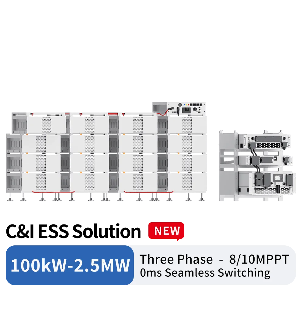
Displayed solution architectures
Separate STS-backed and AC-DC modular routes
The two pages use different conversion and transfer concepts. Their switching, overload, PV, battery and included-equipment statements must remain tied to the exact source configuration.
PCS + MPPT + STS route
The displayed concept references 100/125 kW PCS, a 200 kW MPPT module and 500 kW STS. Confirm the approved one-line, STS topology/rating, backed bus, bypass, protection and transfer conditions.
PCS + MPPT + AC-DC route
The second concept references 100/125 kW PCS, 200/250 kW MPPT and 80 kW AC-DC. Confirm DC- and AC-coupled paths, retrofit intent, auxiliary supply, transfer architecture and exact modules.
257 kWh battery-cluster building block
Source pages reference BOS-B Pro-A3 257 kWh clusters and modular expansion. Verify exact battery revision, usable energy, voltage/current, BMS, permitted cluster count, enclosure and fire/thermal scope.
100 kW to 2.5 MW project scaling
A source scaling range is not a released project design. PCS quantity, AC bus, transformer, protection, fault level, battery ratio, EMS, redundancy, layout and commissioning require engineering.
C&I ESS project checks
Six workstreams before requesting a modular C&I ESS quotation
A bankable request defines operating objectives, power/energy, topology, site interfaces, safety and contractual scope before selecting modules.
Use case and operating modes
State backup, peak shaving, demand management, self-consumption, zero export, microgrid or another objective plus load profile, critical bus, outage behavior and control priority.
Power, energy and duration
Provide kW, kWh and required duration with load/dispatch assumptions, usable SoC window, losses, temperature, degradation, reserve, overload and future expansion basis.
PV, PCS and coupling topology
Provide PV/MPPT or AC-coupled design, existing equipment, DC and AC voltages, PCS quantity, common bus, AC-DC modules, STS/bypass and generator/grid interfaces.
Battery, BMS and EMS hierarchy
Confirm exact cluster model/revision, quantity, voltage/current, BMS levels, communications, PCS pairing, EMS functions, meters/CTs, SCADA and cybersecurity/access responsibilities.
Grid, switchgear and site engineering
Define transformer, MV/LV switchgear, protection/selectivity, earthing, fault level, grid studies, fire strategy, HVAC, auxiliaries, civil works, layout, access and authority route.
Documents, delivery and commissioning
Request approved one-line/BOM, calculations/studies scope, exact manuals/certificates, FAT/SAT, packing/phasing, installation, commissioning, training, warranty, service, spares and exclusions.
Integration and contract boundaries
A modular solution page is not a complete EPC or performance guarantee
Final capability depends on the released combination, project design, site, controls, grid and contracted supply/services. Keep every scope boundary explicit.
Architecture labels are not included scope
PCS, MPPT, STS, AC-DC, batteries, EMS, switchgear, transformer, HVAC/fire, auxiliaries and civil works must each be marked included, optional, excluded or supplied by others.
Transfer and overload claims are exact-route evidence
Any 0 ms, under-10 ms or short-duration overload statement applies only to the named topology, load conditions, battery/DC capability, settings, test basis and released configuration.
Cluster count does not guarantee project performance
Energy, duration, power, efficiency, cycle life and availability depend on SoC window, C-rate, temperature, losses, degradation, controls, redundancy and warranty conditions.
Fire features are not site approval
Cell chemistry or module-level aerosol statements do not replace project hazard analysis, detection/suppression design, ventilation, separation, egress, emergency response and authority acceptance.
Continue the project review
Connect modular ESS architecture to C&I operating objectives
Use the hybrid solution to define the site case, then use the sizing guide to document kW, kWh, duration and reserve assumptions.
Commercial solar and storage hybrid solution
Review how PV, PCS/inverters, batteries, controls, switchgear, site works and local professional responsibilities form one C&I project.
Review solution context
Battery storage sizing guide
Use load, duration, usable energy, power, efficiency, degradation, reserve and operating-mode checks before fixing a modular system size.
Read the buyer guide
Deye modular C&I ESS FAQ
Questions to close before selecting a C&I ESS architecture
These answers support procurement; final electrical, battery, controls, fire, civil, grid and commissioning decisions remain project-specific.
What is the difference between the two displayed Deye modular C&I ESS routes?
One source page describes 100/125 kW PCS with a 200 kW MPPT module and 500 kW STS; the other describes 100/125 kW PCS with 200/250 kW MPPT and an 80 kW AC-DC module. Confirm the exact one-line, transfer/coupling intent, modules and project scope rather than treating them as variants of one SKU.
Does the 100 kW–2.5 MW label define a complete system size?
No. It is a displayed modular solution range. Final PCS quantity, battery clusters, duration, PV/AC coupling, bus/transformer, fault and protection design, controls, redundancy, site layout and grid approval must be engineered and released for the project.
Does a 257 kWh battery cluster provide 257 kWh of usable project energy?
Not necessarily. Confirm nominal versus usable energy, SoC window, current/C-rate, temperature, auxiliaries, conversion losses, degradation, reserve, warranty and control limits for the exact cluster and system configuration.
What should a Deye modular C&I ESS RFQ include?
Include load/dispatch profile, backup or grid objective, kW/kWh/duration, PV and AC topology, voltage/transformer, STS/AC-DC/PCS/cluster concept, EMS/SCADA, protection/grid studies, fire/civil/site scope, documents, FAT/SAT, commissioning, service and delivery phasing.
Deye modular C&I ESS procurement
Deye Modular C&I ESS Concepts for Hybrid and Backup Projects
Compare two displayed 100 kW–2.5 MW C&I ESS solution pages. Both source concepts reference 100/125 kW PCS and 257 kWh BOS-B Pro-A3 battery clusters, while one route describes 200 kW MPPT plus 500 kW STS and the other describes 200/250 kW MPPT plus 80 kW AC-DC. These are modular solution architectures, not one fixed turnkey SKU. Confirm load mode, PV/AC coupling, battery clusters, switching, EMS, fire strategy, switchgear, transformer, civil scope, grid studies, commissioning and contractual boundaries.
Prepare a Deye modular C&I ESS RFQ by operating architecture
Send the load and modes, kW/kWh/duration, PV/AC coupling, voltage and grid, PCS/MPPT/STS or AC-DC concept, battery/EMS, site/fire/civil scope, documents, commissioning and delivery plan.