
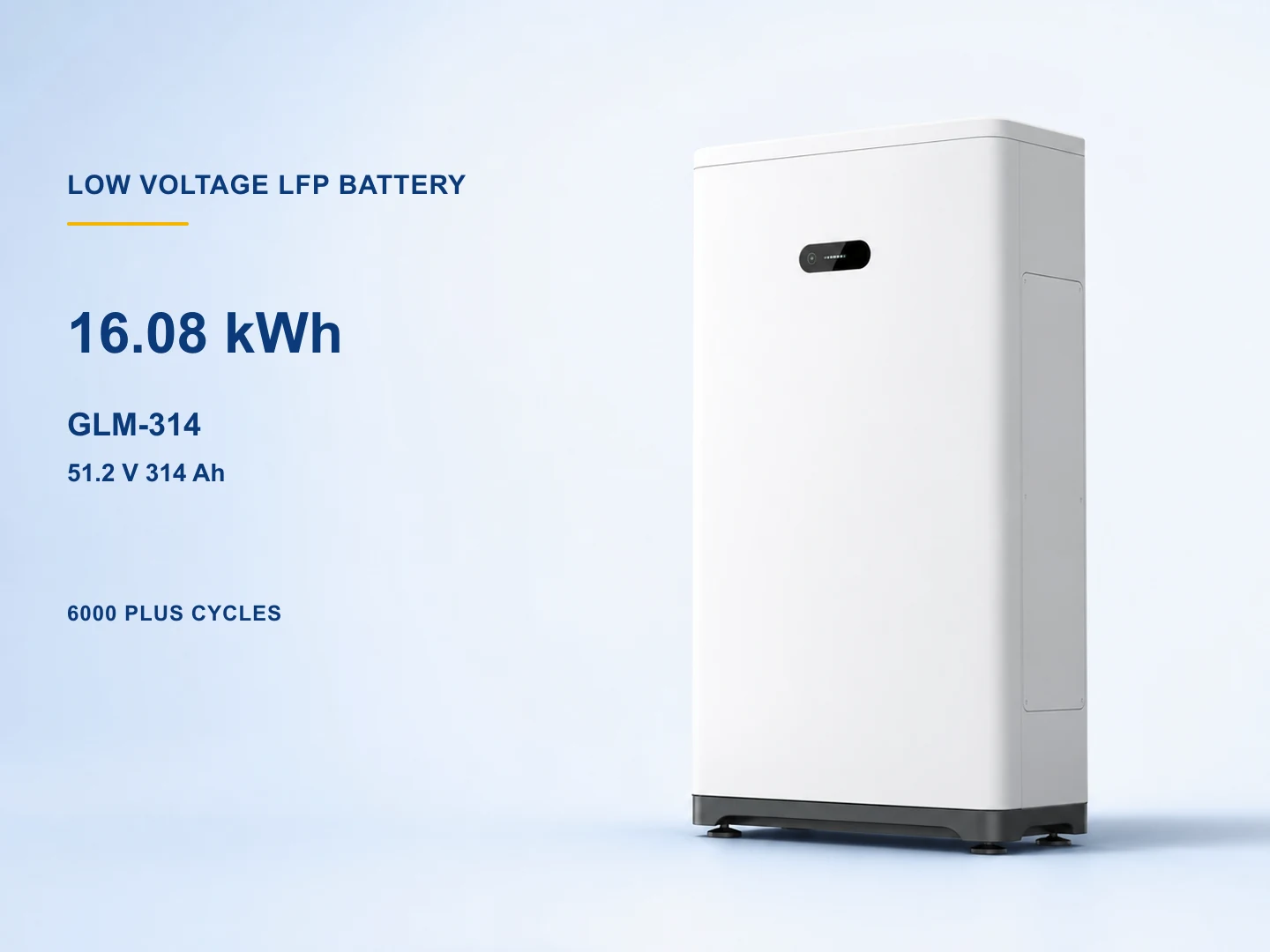
GLM-314 / GLM-280 Low-Voltage LFP Battery
16.08 kWh / 14.34 kWh low-voltage lfp battery for high-capacity residential storage and small commercial solar-plus-storage.
CEEMCUN38.3
View DetailsOpen an exact page for its source-derived configuration, then confirm the final capacity variant, battery-bank design, BMS and inverter pairing, accessories, files, installation, transport conditions, warranty, availability, and order terms.
16.08 kWh / 14.34 kWh low-voltage lfp battery for high-capacity residential storage and small commercial solar-plus-storage.
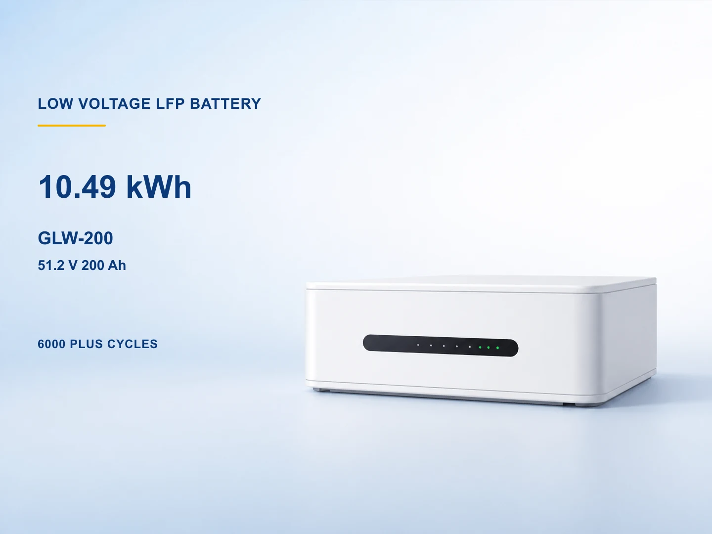
10.49 kWh low-voltage lfp battery for residential solar storage and backup-capable hybrid systems.
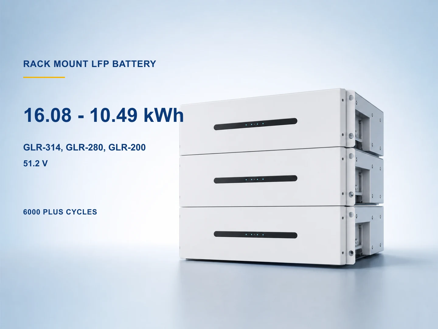
16.08 kWh / 14.34 kWh / 10.49 kWh rack-mount low-voltage lfp battery for residential multi-battery banks and light commercial backup storage.
View Details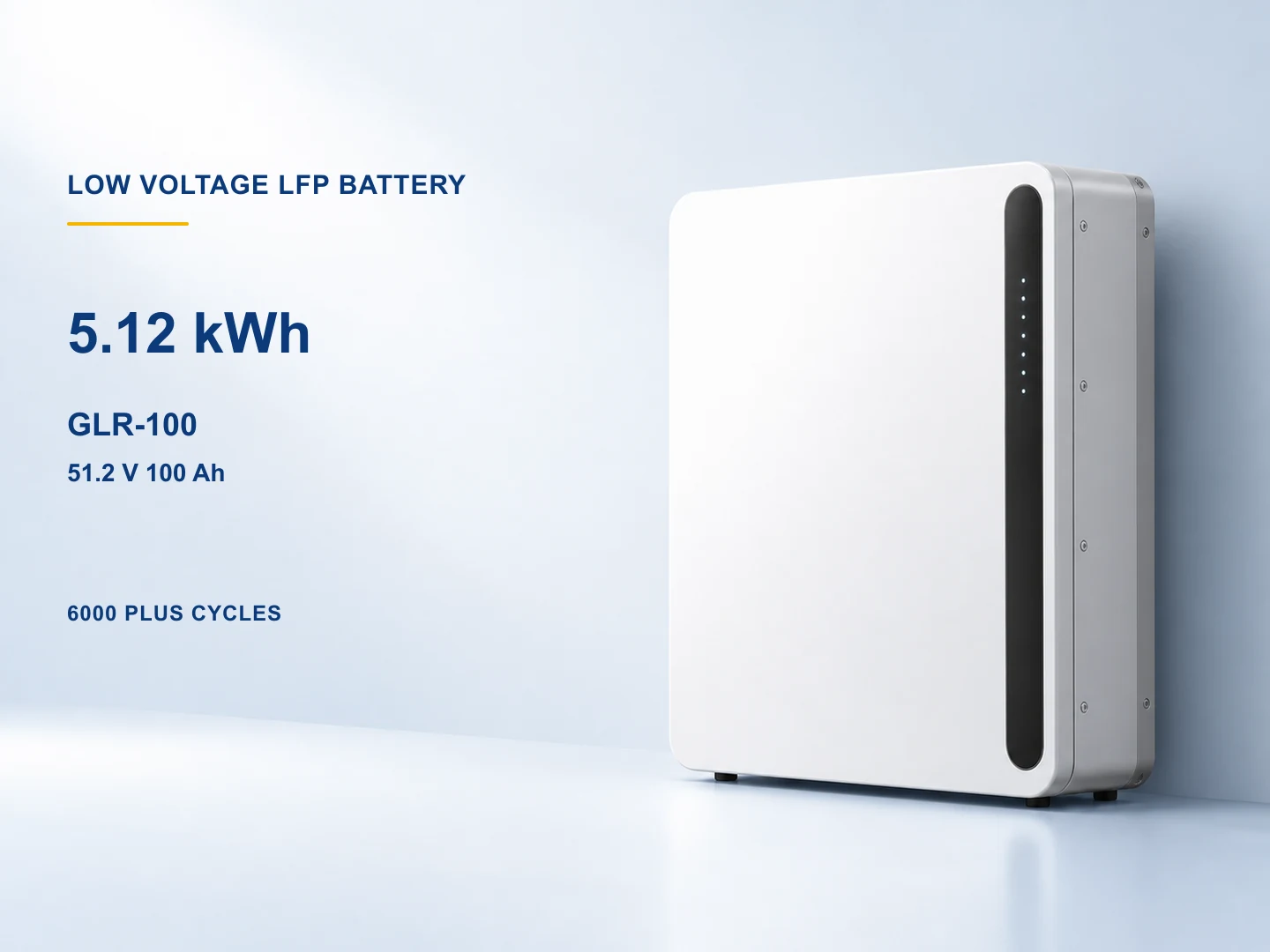
5.12 kWh rack / wall / stand-mount low-voltage lfp battery for modular home backup and compact off-grid battery banks.
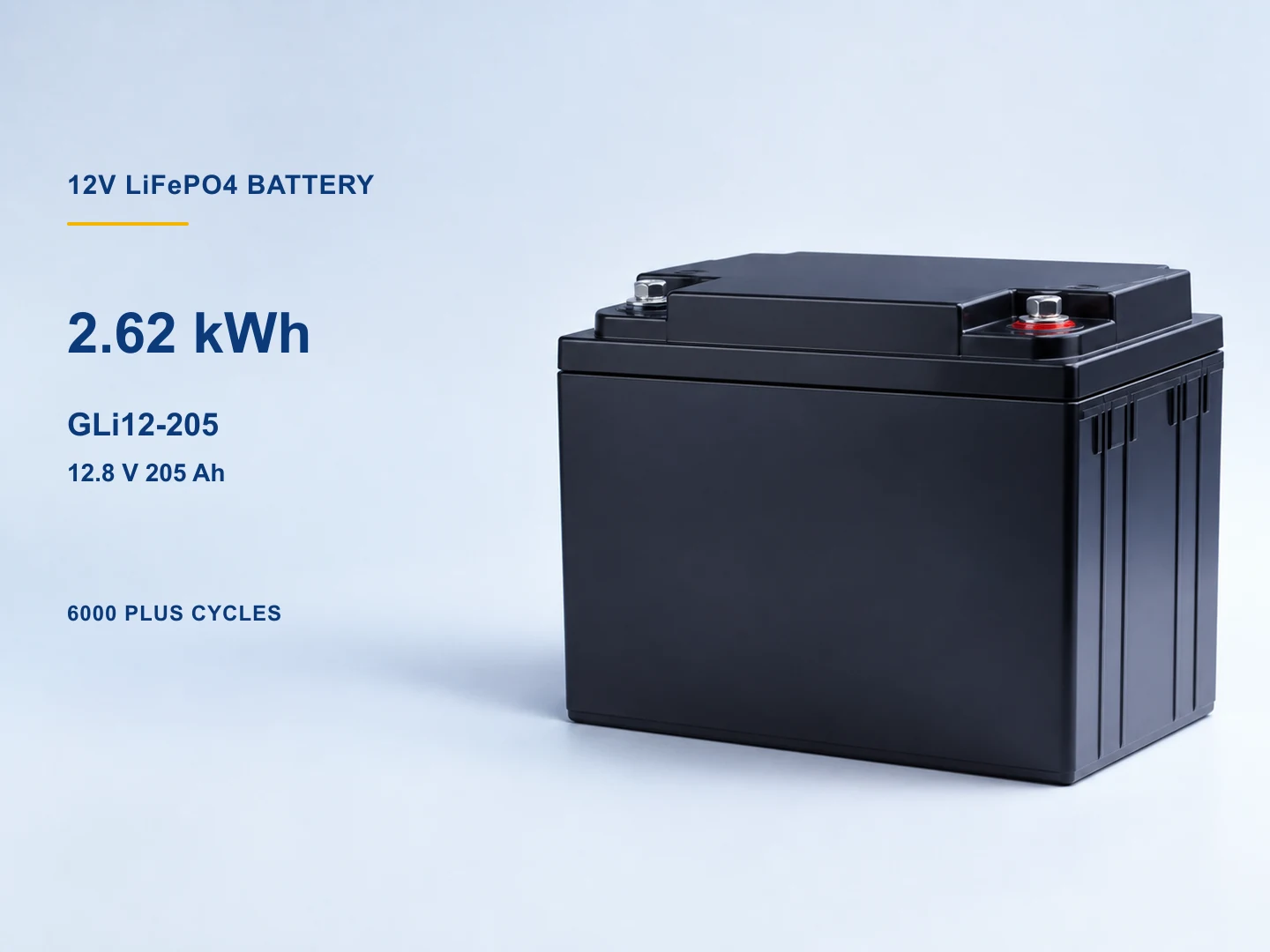
2.62 kWh 12 v low-voltage lfp battery for off-grid, telecom backup, marine and lead-acid replacement projects.
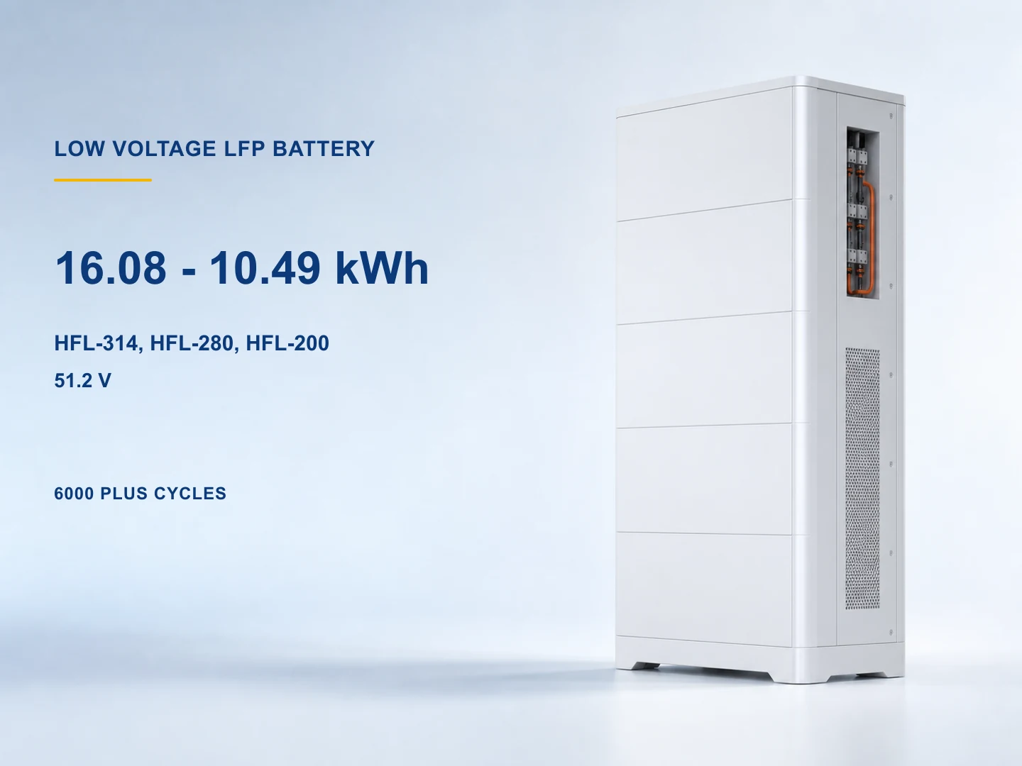
16.08 kWh / 14.34 kWh / 10.49 kWh low-voltage lfp battery for high-capacity home storage and small commercial solar backup.
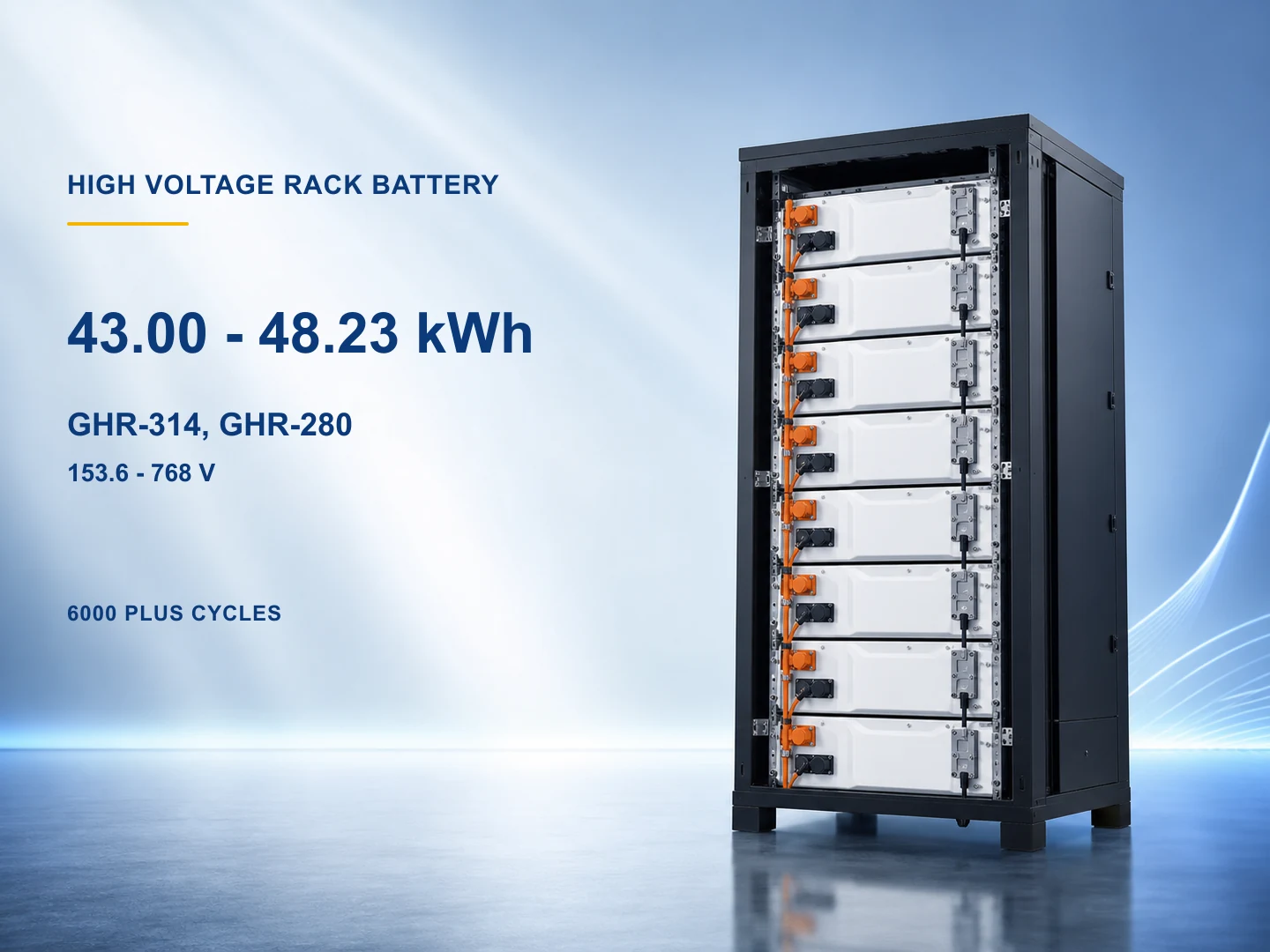
48.23–241.15 kWh / 43.00–215.04 kWh system range high-voltage rack lfp battery for high-voltage hybrid systems and commercial backup storage.
View Details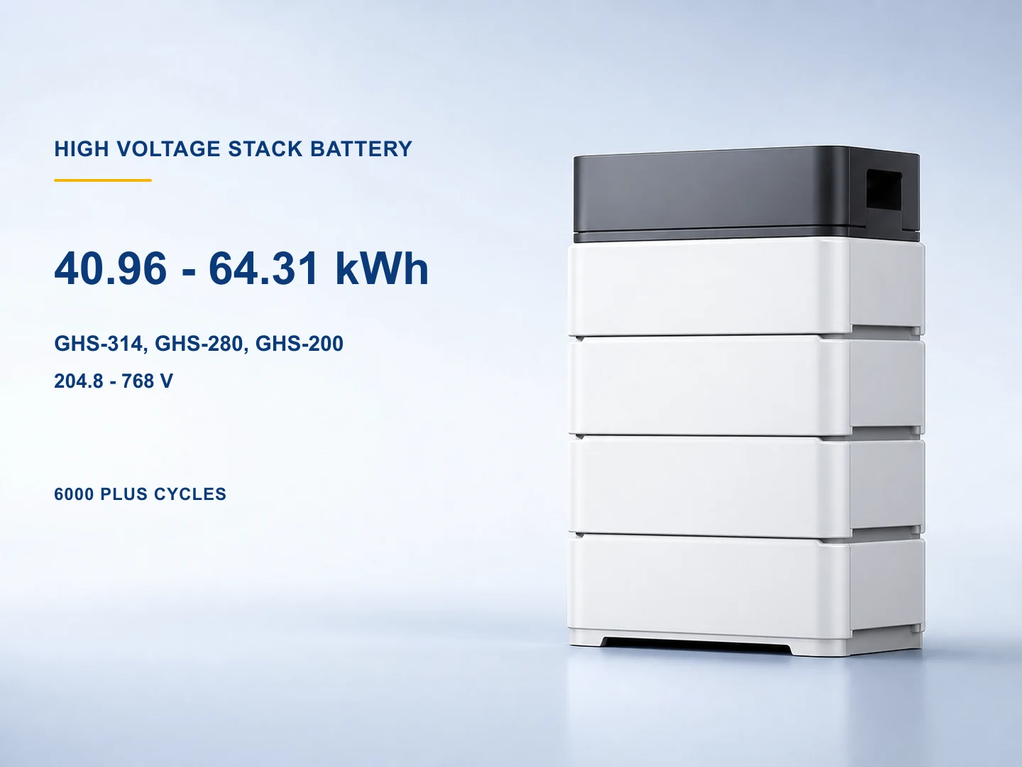
40.96–241.15 kWh system range, by configuration high-voltage stack lfp battery for large residential systems and commercial high-voltage energy storage.
View Details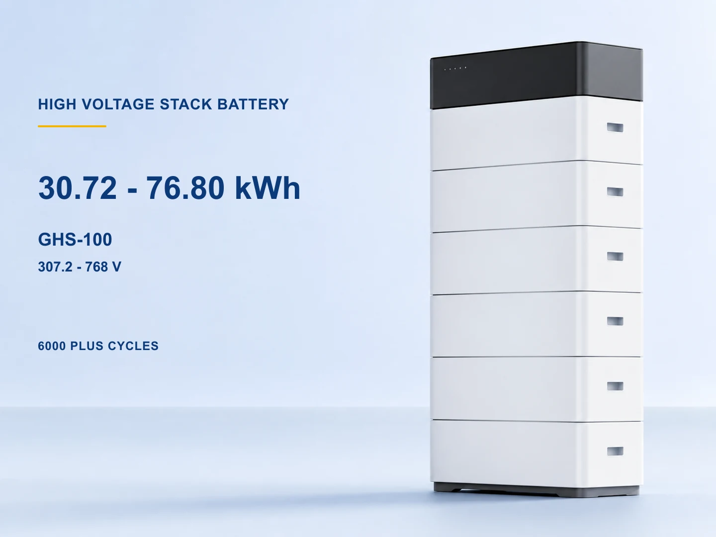
30.72–76.80 kWh system range high-voltage stack lfp battery for modular high-voltage residential storage and light commercial backup.
View Details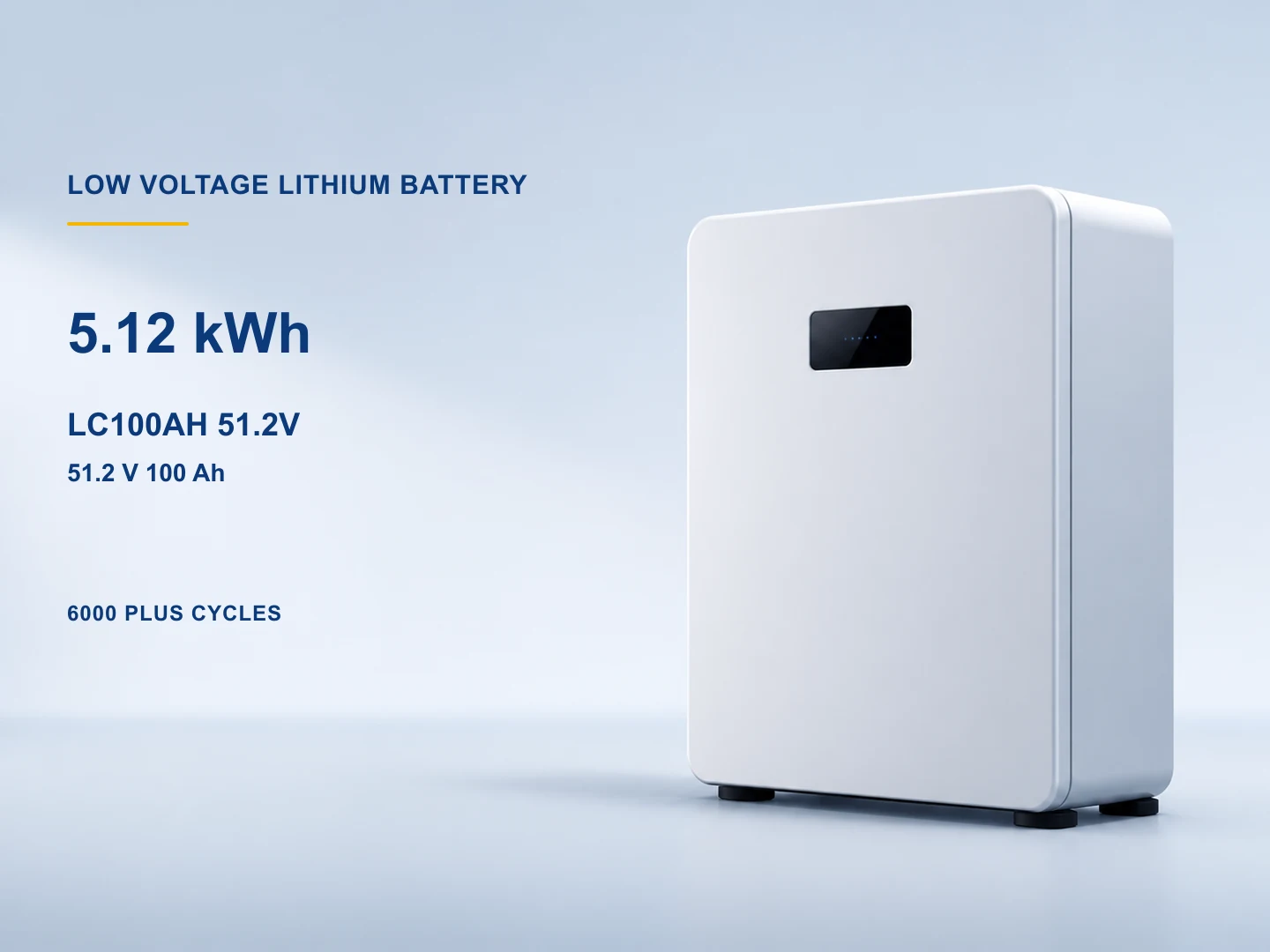
5.12 kWh low-voltage lithium energy storage battery for residential solar storage and low-voltage backup systems.
View DetailsThe current pages span four battery roles. A similar chemistry, nominal voltage, capacity, or module enclosure does not prove that products can be mixed, paralleled, placed in series, connected to the same inverter, or installed in the same environment.
One 205 Ah page for selected 12/24/48 V off-grid, telecom, marine, or replacement projects. Series and parallel permission, charger profile, current, cables, fusing, enclosure, and BMS behavior need confirmation.
Six rack, wall, stand, and floor-enclosure pages with 100–314 Ah options. Compare current, mounting, IP rating, communications, parallel limits, inverter protocol, and exact capacity variant.
One 153.6–768 V system page built from 51.2 V modules. Series count, PDU, rack, isolation, current, inverter window, CAN protocol, protection, and qualified commissioning form one approved package.
Two stack-system pages with different module capacities and minimum series counts. Final voltage, energy, PDU or control unit, mechanical stack, BMS protocol, inverter, and accessories must match.
A battery bank must be selected as an electrical, control, mechanical, thermal, safety, and documentation system. Nominal voltage and kWh are useful filters but cannot establish compatibility, runtime, installation suitability, or commercial warranty.
Define residential, off-grid, telecom, backup, C&I, replacement, or expansion use; required power, usable energy, autonomy, duty cycle, grid or generator behavior, and future expansion.
Confirm LFP chemistry, nominal and operating voltage, module count, series or parallel rules, PDU or master control, DC isolation, pre-charge, protection, earthing, and compatible inverter window.
Review Ah, nominal and usable kWh, recommended and maximum charge/discharge current, C-rate, DoD basis, temperature limits, derating, cell balancing, reserve, and load peaks.
Match CAN or RS485 protocol, pinout, firmware, inverter battery profile, master and slave addressing, parallel or series control, alarms, shutdown behavior, monitoring, and written compatibility evidence.
Confirm dimensions, mass, rack or wall loading, stack hardware, IP class, indoor or outdoor enclosure, ventilation, clearance, cable route, terminals, lifting, seismic restraint, access, and service replacement.
Request exact-model datasheet, manual, label, SDS, UN 38.3 evidence where applicable, certificates, warranty terms, cycle-test basis, packing, dangerous-goods details, origin, serial traceability, and order revision.
The displayed pages are source-derived battery configurations. Final model variant, bank design, inverter pairing, BMS firmware, enclosure, protection, installation, transport acceptance, warranty, availability, and commercial terms require exact-project confirmation.
Inverter or PCS, protection, isolation, PDU, rack or enclosure, EMS, switchgear, cooling, fire strategy, cables, installation, commissioning, and local approvals may be separate.
Runtime depends on usable DoD, load profile, surge, inverter and cable losses, reserve, temperature, aging, BMS limits, charge state, auxiliary loads, and operating strategy.
A cycle figure applies to stated temperature, C-rate, DoD, end-of-life threshold, test method, and configuration. Commercial years, throughput, exclusions, remedies, and claim process require warranty terms.
Transport evidence has a defined product and test scope. Carrier acceptance still depends on model, quantity, packing, route, mode, documents, and current instructions; site safety and electrical approval are separate.
Use the solution page to define loads and backup purpose, then use the compatibility guide to verify voltage, current, protocol, firmware, protection, and approved pairing before selecting a module bank.
Define critical loads, autonomy, PV, inverter role, battery usable energy and power, protection, installation, documents, and supply responsibility before sizing modules.
Review backup solution
Review voltage window, charge and discharge current, CAN or RS485 protocol, firmware, approved list, protection, cables, commissioning, and written pairing evidence.
Read compatibility guide
These answers establish an RFQ starting point. Final bank engineering, inverter compatibility, protection, enclosure, installation, transport, local approval, commissioning, and warranty review remain project-specific.
Not automatically. Compare the exact operating voltage, recommended and maximum current, CAN or RS485 protocol and pinout, firmware, inverter battery profile, approved-model evidence, capacity, parallel control, protection, cables, alarms, shutdown behavior, commissioning settings, and warranty conditions.
Start with the inverter DC window and system design. Compare series or parallel arrangement, module count, current, power, PDU or master controller, BMS protocol, isolation, protection, cable size, enclosure, installation qualification, service strategy, usable energy, and expansion rules—not nominal voltage alone.
Only under an unrealistic constant 1 kW assumption with no losses or reserve. Real runtime depends on usable DoD, inverter efficiency, load variation and surge, battery power limits, temperature, aging, BMS reserve, state of charge, cables, and auxiliary consumption. Use a load schedule and operating objective.
Include application, load power and energy objective, inverter make and model, low- or high-voltage architecture, capacity and expansion target, quantity, series or parallel plan, BMS protocol, installation environment, rack or enclosure, protection, required datasheet and transport files, destination, warranty request, and delivery target.
Compare 10 displayed LFP battery module and pack pages spanning 12.8 V standalone, 51.2 V low-voltage rack and enclosure, and high-voltage rack or stack architectures. Review the exact model for capacity, nominal energy, operating voltage, charge and discharge current, series or parallel limits, BMS communication, dimensions, mass, installation environment, cycle test conditions, transport evidence, and compatible inverter requirements before defining a battery bank.
Send the application, load and autonomy target, inverter, voltage architecture, kW/kWh, module count, BMS protocol, installation, enclosure and protection, documents, destination, quantity, and schedule. Final compatibility, model, price, availability, warranty, and lead time are confirmed in the quotation.