
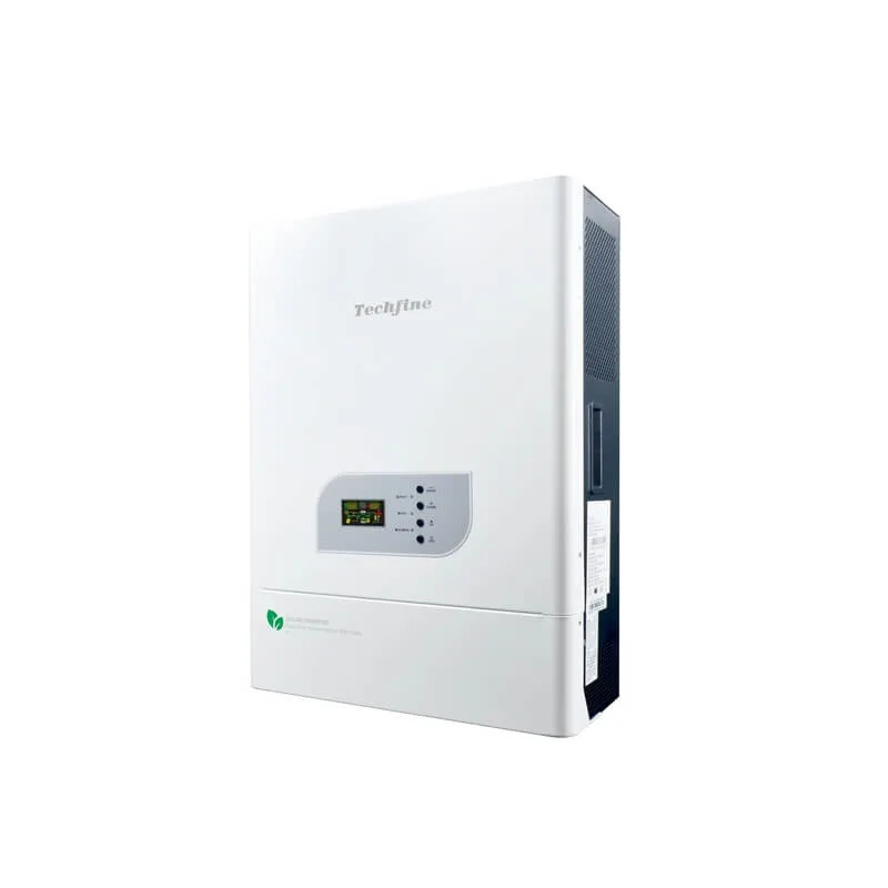
Techfine VS-N 3–10 kW split-phase off-grid inverter: Verify Battery, PV and Load Configuration
This page organizes the current source table for the Techfine VS-N 3–10 kW split-phase off-grid inverter. 3–10 kW table members; 110/220 V input/output route must be selected. It does not turn a family range, voltage label or inverter/charger headline into a complete off-grid system design.
Current source route: VS-N 3–10 kW split-phase off-grid inverter.
Current source parameter table
This table is preserved from the current source record. Read it with the identity, compatibility and document boundaries below; unresolved conflicts are not corrected by assumption.
| Model | 3024/48 | 5024/48 | 6324/48 | 7548 | 8048 | 10048 | 12548 |
|---|---|---|---|---|---|---|---|
| Power Input | 220VAC (Standard) / 110VAC (Custom) | ||||||
| input Voltage Range | 220V Model: 154–264VAC ±3V (Normal Mode), 185–264VAC ±3V (UPS Mode) 110V Model: 77–132VAC ±3V (Normal Mode), 92–132VAC ±3V (UPS Mode) | ||||||
| Input Frequency | 50/60Hz±5% | ||||||
| Rated Output Power | 3000W | 4000W | 5000W | 6000W | 6400W | 8000W | 10000W |
| Output Voltage (Grid Mode) | For 110V Input Dual-Output Units: • 110V Dual Output: Output voltage = Input voltage • 220V Single Output: Output voltage = 2× Input voltage For 220V Input Dual-Output Units: • 110V Dual Output: Output voltage = ½ Input voltage • 220V Single Output: Output voltage = Input voltage | ||||||
| Output Frequency (Grid Mode) | Same as input frequency | ||||||
| Output Voltage (Inverter Mode) | • 220V Single Output: 220VAC ±10% • 110V Dual Output: 110VAC ±10% | ||||||
| Output Frequency (Inverter Mode) | 50Hz or 60Hz ±1% | ||||||
| Output Waveform (Inverter Mode) | Sine Wave | ||||||
| Battery Type | External Lead-Acid / Flooded / Lithium Battery | ||||||
| Battery Voltage | 12VDC / 24VDC / 48VDC | ||||||
| Battery Charging Voltage | 13.7VDC / 27.4VDC / 54.8VDC | ||||||
| Maximum PV Array Power | High-Current Solution (150V/120A): • 24V: 3200W / 48V: 6400W High-PV Solution (245V/100A): • 24V: 2700W / 48V: 5400W | ||||||
| PV Input Voltage Range (PWM/MPPT) | High-Current Solution: • 24V: 30–150VDC / 48V: 60–150VDC High-PV Solution: • 24V: 30–245VDC / 48V: 60–245VDC | ||||||
| Max PV Open-Circuit Voltage | • High-Current: 150VDC • High-PV: 245VDC | ||||||
| Optimal Vmp Operating Range | High-Current: • 24V: 30–105VDC / 48V: 60–105VDC High-PV: • 24V: 30–170VDC / 48V: 60–170VDC | ||||||
| Max Solar Charging Current | • High-Current: 120A • High-PV: 100A | ||||||
| Max AC Charging Current | 63A (Default 50A) / 31A (Default 25A), | 83A (Default 66A) / 41A (Default 33A), | 104A (Default 83A) / 52A (Default 42A) | 62A (Default 50A) | 66A (Default 53A) | 83A (Default 66A) | 104A (Default 83A) |
| Transfer Time | ≤10ms (UPS Mode) / ≤20ms (INV Mode) | ||||||
| Surge Capacity | (MAX) 3:1 | ||||||
| Standby Power (W) | • Toroidal Transformer: • 12V Unit: 8W / 24V Unit: 16W / 48V Unit: 32W | ||||||
| Protection Features | • Grid Mode: Input overcurrent protection (non-fuse breaker) • Inverter Mode: Overload, short-circuit, low-voltage, reverse polarity protection (fuse) | ||||||
| Status Display | • Dot-matrix screen + LEDs / Color segment screen + LEDs • Page-turning keys to view parameters: AC voltage/frequency, PV voltage/current, output voltage/frequency, battery voltage, load current, etc. • LEDs indicate grid/charging/inverter/fault status. | ||||||
| Operating Temperature | -10°C to 50°C | ||||||
| Storage Temperature | -15°C to 45°C | ||||||
| Humidity | 10–90% non-condensing | ||||||
| Noise Level | <45dB | ||||||
| Dimensions (L×W×H) | 545 × 400 × 175 mm | ||||||
Current document status
Request the exact model/suffix, nameplate, manual, PV/battery settings, wiring diagram, protection schedule and destination evidence before quotation release.
Current table evidence
Keep power, battery and AC rows on the same selected member
An off-grid inverter must be selected against actual loads, PV strings, battery current and site wiring.
Member route
3–10 kW table members; 110/220 V input/output route must be selected
PV and charger
Confirm MPPT or PWM type, PV cold Voc, operating window, PV watts, charge current and each exact-model limit.
Battery route
Confirm nominal voltage, chemistry, BMS/current limits, charge settings, temperature and the exact approved battery configuration.
AC and load route
Confirm input/source, output voltage/phase, continuous and surge loads, generator, transfer/bypass behavior, neutral and grounding.
Off-grid RFQ checks
Six checks before finalizing the inverter
Define the whole electrical route rather than selecting from a headline VA or watt number.
Exact code
Request model/suffix, nameplate and the applicable table row.
Load duty
List continuous watts/VA, power factor, motor start current, surge duration and critical circuits.
Battery
Fix voltage, chemistry, capacity, BMS, charge/discharge current, reserve and temperature.
PV
Provide module data, cold Voc, series/parallel layout, charger type and protection.
AC source and output
Confirm voltage, frequency, phase, generator, bypass/transfer, outlets and wiring.
Evidence
Request manual, wiring, settings, protection, supplied accessories, compliance evidence, warranty and commercial terms.
System boundaries
An inverter charger is not a complete off-grid system
Final performance and safety depend on the selected member plus PV, battery, load, protection and installation design.
Family boundary
Do not transfer watts, PV input, battery voltage, transfer time or optional functions across family members.
Battery compatibility
Voltage or lithium wording does not prove BMS pairing, current limits, charge settings or warranty approval.
PV and protection
Rated PV watts do not replace cold-Voc, MPPT/PWM, string protection, cable, isolator, SPD and grounding checks.
AC behavior
UPS, bypass, split-phase and generator labels require the exact manual and a load-specific acceptance test.
Continue the system review
Prepare an evidence-based off-grid RFQ
Record real loads, battery and PV inputs before asking for a final configuration.
Off-grid inverter FAQ
Questions to close before quotation
The exact member and installation design remain decisive.
Which rating applies to this VS-N 3–10 kW split-phase off-grid inverter?
Use the exact quoted model and its table row. The current family record is 3–10 kW table members; 110/220 V input/output route must be selected.
Can any same-voltage battery be used?
No. Confirm battery chemistry, BMS, current, charge settings, temperature and exact-model approval.
Does the inverter headline prove backup or generator compatibility?
No. Confirm source, bypass/transfer, load surge, AC wiring and generator behavior from the exact manual.
What documents should the RFQ include?
Request exact datasheet/manual, nameplate, wiring, PV/battery settings, protection schedule, compliance evidence, BOM and warranty.
Prepare a verified VS-N 3–10 kW split-phase off-grid inverter RFQ
Send load schedule, AC source, PV string, battery/BMS, operating environment and destination evidence requirements.
Verify Off-grid ConfigurationRelated products
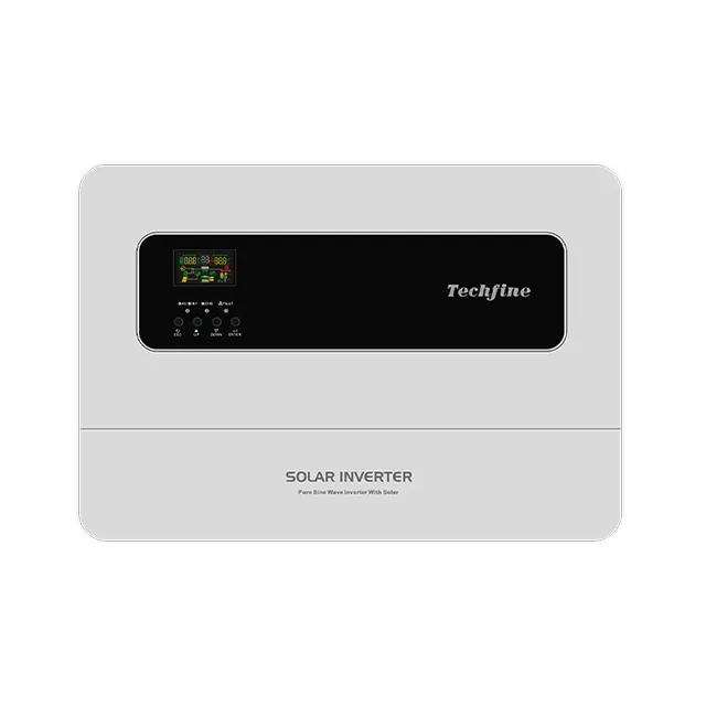 Off Grid Solar Inverter
JV-series | 3kW/4kW/5kW high PV off-grid solar inverter with MPPT charger
Low no-load loss, less than half of the high-frequency machine with the same power
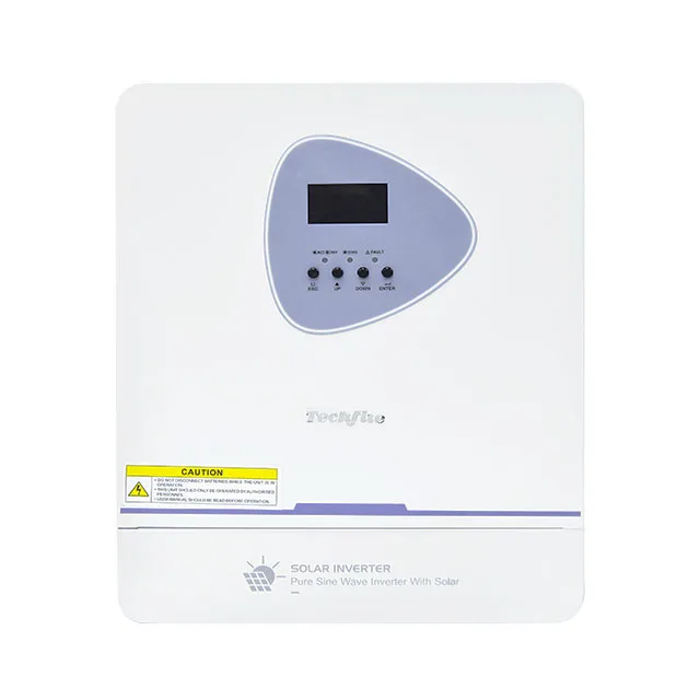 Off Grid Solar Inverter
EA-series | 1.6kW/3kW high frequency off-grid solar inverter with MPPT charger
Multiple parameters can be adjusted according to user needs to adapt to different occasions
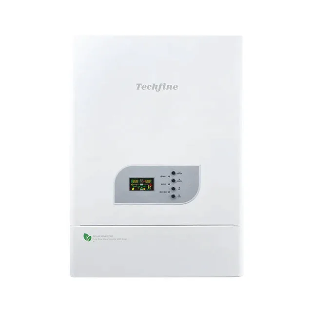 Off Grid Solar Inverter
VS PRO PLUS-series | 5kW/10kW 6300VA/12500VA off-grid solar inverter support parallel
Parallel Function Up to Maximum 9 units