
Why does a solar battery show 100% but deliver no power?
A full battery icon is only useful when the inverter is receiving current data and the BMS still permits the battery to charge and discharge.
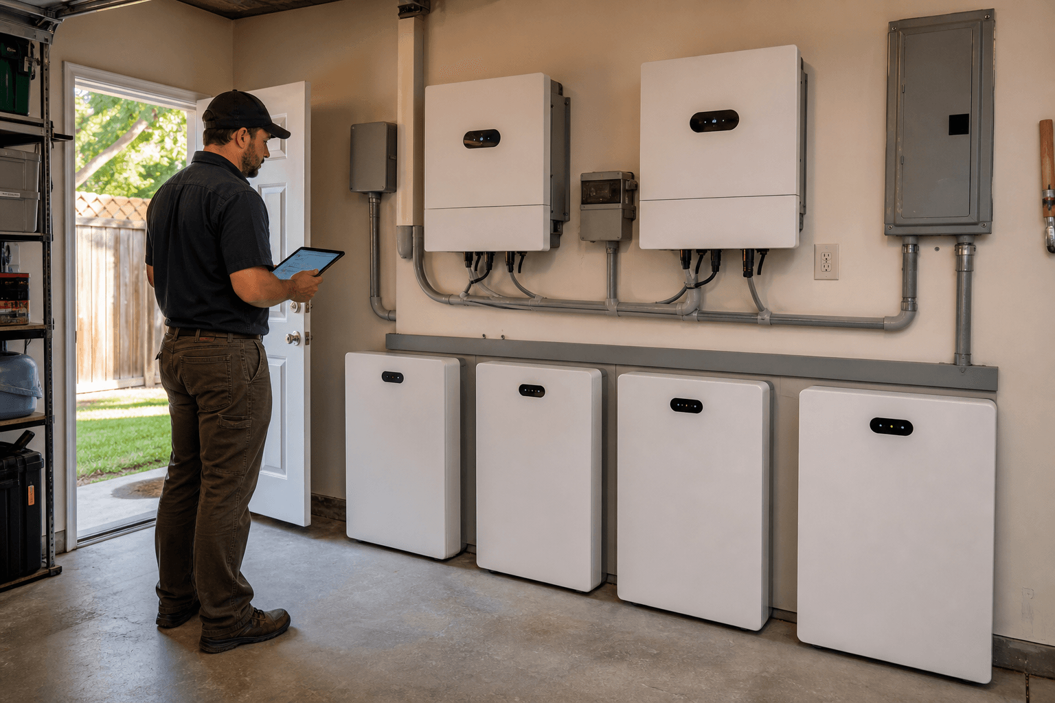
A battery display that jumps from 2% to 100% after an outage is not a reason to celebrate. If the loads are still off and the inverter's battery-information page is blank or full of zeros, the useful question is: where did that 100% figure come from?
The battery may still place DC voltage at the inverter terminals while its BMS has withdrawn permission to discharge. The inverter may be holding an old state-of-charge value, estimating from voltage, or falling back to a placeholder after communication is lost. Those possibilities can look similar on one screen, but they lead to different service decisions.
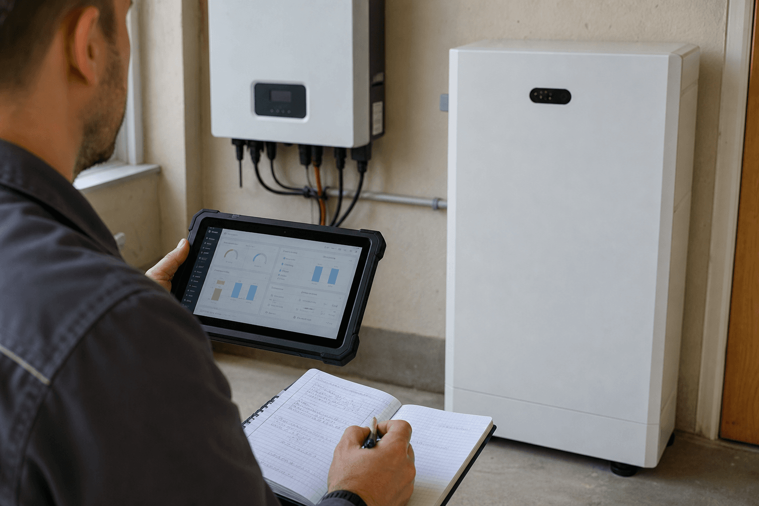
This guide helps an owner, installer or support team assemble the evidence before changing equipment or settings. It is not a battery-recovery procedure. A low-voltage or protected lithium battery must be handled according to the exact battery and inverter documentation, with the manufacturer or a qualified local service provider involved where required. The photographs are illustrative editorial images rather than Rongkai project records.
The 100% figure may not be a live battery measurement
An inverter screen can group several different signals under the word "battery." Terminal voltage is an electrical measurement at that moment. SOC is an estimate maintained by the BMS or, in some modes, by the inverter. Charge permission, discharge permission and current limits are separate data. One can still appear while another is missing.
A healthy closed-loop connection normally carries more than a percentage. If the inverter sees DC voltage but the BMS fields are zero, that is a communication clue rather than proof that the cells are full, empty or damaged. Check the timestamp too: a cloud dashboard may retain the last valid value after the local equipment has stopped reporting.
- What you see
- DC voltage is present
- What it can tell you
- The inverter can detect voltage at its battery input.
- What it cannot prove
- The BMS permits discharge or the bank has usable energy.
- What you see
- SOC reads 100%
- What it can tell you
- The screen has received, estimated or retained a percentage.
- What it cannot prove
- The percentage is current and came from a healthy BMS link.
- What you see
- BMS fields show zero
- What it can tell you
- Expected battery data may be missing from the inverter.
- What it cannot prove
- The battery cells are damaged or completely empty.
- What you see
- Battery icon or alarm changes
- What it can tell you
- The system has detected a state worth checking in its alarm history.
- What it cannot prove
- Which device or communication path caused it.
| What you see | What it can tell you | What it cannot prove |
|---|---|---|
| DC voltage is present | The inverter can detect voltage at its battery input. | The BMS permits discharge or the bank has usable energy. |
| SOC reads 100% | The screen has received, estimated or retained a percentage. | The percentage is current and came from a healthy BMS link. |
| BMS fields show zero | Expected battery data may be missing from the inverter. | The battery cells are damaged or completely empty. |
| Battery icon or alarm changes | The system has detected a state worth checking in its alarm history. | Which device or communication path caused it. |
Use the exact equipment manuals to interpret each field. This table is a reading guide, not a fault diagnosis.
Write down the outage sequence before clearing it
The order of events often says more than the final screen. Capture the SOC before the outage, reserve and shutdown settings, active loads, first alarm and what changed when the grid returned. In a multi-inverter installation, note whether both units lost the same battery data at the same time.
The programmed reserve and the BMS's final protection threshold may be separate controls. Temperature, an individual cell limit, current, communication loss or a load-qualification check can also affect whether the battery permits operation. Save screenshots and logs before an approved restart or recovery step removes that context.
- 1
Capture the event
Save the local SOC, voltage, alarms, grid state and active loads before clearing anything.
- 2
Check the timestamp
Compare the local equipment time with the portal's last update so stale data is not treated as live.
- 3
Read the BMS fields
Look for SOC, permissions, current limits and alarms exposed by the approved interface.
- 4
Separate the networks
In a parallel system, distinguish inverter-to-inverter communication from battery-to-inverter communication.
- 5
Confirm the operating mode
Record whether the exact pairing is using its approved closed-loop or open-loop configuration.
- 6
Escalate with evidence
Send model codes, firmware, configuration and the event timeline to the manufacturer or qualified service party.
Separate the battery state from the communication path
Ask two questions. Is the battery bank awake and willing to charge or discharge? Is the inverter receiving valid data from it? A protection event can stop the first. A protocol, addressing, termination, firmware or communication-path problem can stop the second. Both can follow the same outage, so one voltage reading cannot settle the diagnosis.
Dual-inverter systems have an inverter parallel network and a separate battery BMS path. The manuals decide the leader role, termination and way battery limits reach the other inverter. Several parallel batteries add another layer because the aggregate display can hide one module that is offline or protected. Compare every module through the manufacturer's approved interface rather than treating a network cable as a generic plug-and-play part.
Closed loop and open loop are different operating agreements
In closed-loop operation, a compatible BMS communicates limits and status to the power-conversion equipment. Discover's HELIOS documentation describes the battery requesting charging parameters and publishes separate integration instructions for supported inverter families. Sol-Ark's 18K documentation also treats lithium-battery communication as a defined configuration and identifies loss of BMS communication as a specific fault condition.
Open-loop operation uses a manually configured battery profile and voltage-based controls instead of the same live exchange. It can be approved for some exact pairings, but it does not repair a broken communication path or make a stale SOC trustworthy. If support recommends a temporary mode change, record the original configuration, approved settings source and criteria for returning to closed loop.
Does matching battery voltage prove that BMS communication is working?
No. The inverter can measure DC voltage without receiving SOC, temperature, alarms or charge and discharge limits from the BMS. Check the communication status and data fields defined by the exact equipment manuals.
Will changing to open-loop mode fix a BMS communication fault?
It may provide an approved fallback on some systems, but it does not repair the communication path. It also changes how the inverter controls the battery. Use only the model-specific manufacturer procedure and keep the change documented.
Do not turn a data problem into a battery hazard
Online discussions often propose using another battery, a resistor or an external charger to "wake" a protected lithium bank. That is not a safe universal remedy. The correct recovery path depends on cell condition, contactor state, pre-charge design, terminal voltage, battery firmware and the manufacturer's protection logic. An improvised connection can create high fault current, bypass protection or damage equipment that was trying to remain disconnected.
Do not open battery enclosures, bypass contactors, bridge batteries or apply a charging source that the battery manufacturer has not approved for that exact recovery. If the bank has reached low-voltage protection, been left deeply discharged, shows physical damage, smells unusual, is hot, or will not return to a documented state, stop and escalate to the manufacturer or qualified service party. IEC 62485-5 addresses hazards associated with stationary lithium battery installations; a dashboard anomaly should never be treated as permission to improvise on the DC side.
Can the screen show 100% while the battery has almost no usable energy?
The screen can. A stale, fallback or incorrectly interpreted SOC value can say 100% even though the bank cannot supply the load. Confirm current BMS data and battery permissions before drawing a conclusion from the icon.
Should the owner raise the reserve setting after one deep-discharge event?
Not from the symptom alone. First identify why the normal operating reserve did not prevent the event and compare the present settings with the exact battery and inverter guidance. Reserve, shutdown and BMS protection thresholds may be separate controls.
A useful support packet is short and specific
Support is much faster when the first message contains the exact system and event instead of only "battery says 100%." Include the full inverter and battery model codes, module count, communication accessory, firmware, operating mode and a simple connection overview. Add dated screenshots of every relevant local page and the alarm history.
State what has already been tried and whether it changed battery voltage, communication fields, alarms or contactor status. If there are two inverters, list the leader and follower roles exactly as configured. If there are several battery modules, include the module-level status available through the approved service tool. This gives the manufacturer or installer enough evidence to choose the next documented check without guessing from a percentage.
- Complete inverter and battery model codes, serial ranges where appropriate, module quantity and system age.
- Current firmware, operating mode, communication protocol, gateway or adapter, and documented leader/follower roles.
- Timestamped local screenshots showing SOC, voltage, current limits, BMS fields and alarm history.
- A brief outage timeline and a list of approved recovery steps already attempted.
Related Articles
How do solar panels perform in clouds, heat, salt air and dust?
A panel's watt rating cannot describe every site. Learn what changes in cloudy, hot, coastal and dusty locations, and which details belong in a supply quote.
Read Article→
How to compare solar battery specifications before buying
Two batteries with the same kWh label can do different jobs. Here is how to read the numbers, check the missing details and compare like-for-like quotes.
Read Article→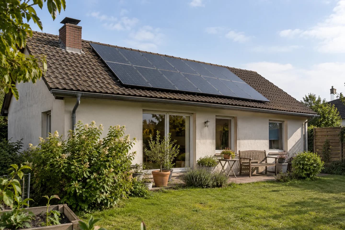
Solar self-consumption and grid export: what equipment do you need?
For project buyers, installers and distributors: what to source as an equipment package, what to arrange locally, and what a useful supply quote should include.
Read Article→