Mounting configuration review
Asphalt Shingle Roof Solar Mounting for Project RFQ Review
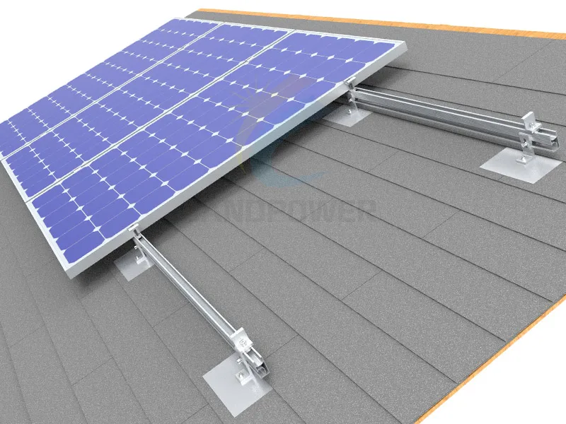
This page identifies the Asphalt Shingle Roof Solar Mounting procurement route. The available catalogue identity does not itself establish dimensions, material grade, finish, module compatibility, design loads, structural calculation, fixing method, installation sequence or certification scope. Freeze the selected configuration against the project drawings and request the evidence needed for that configuration before approving a quotation.
Current source identity: Asphalt Shingle Roof Solar Mounting. The public catalogue label is a starting point for an RFQ, not a released structural design, complete bill of materials or performance approval.
Catalogue identity
Asphalt Shingle Roof Solar Mounting
Selection basis
Project-specific module, interface and layout review required
Engineering basis
Loads, fixing and code scope require project confirmation
Evidence status
Request configuration-specific drawings and documents
Product Details
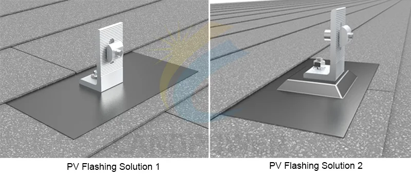
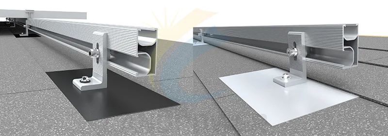
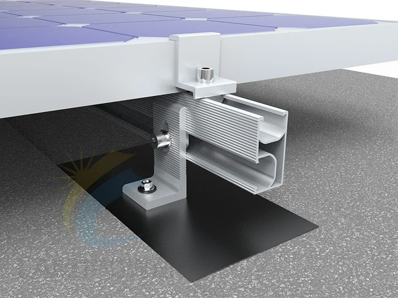
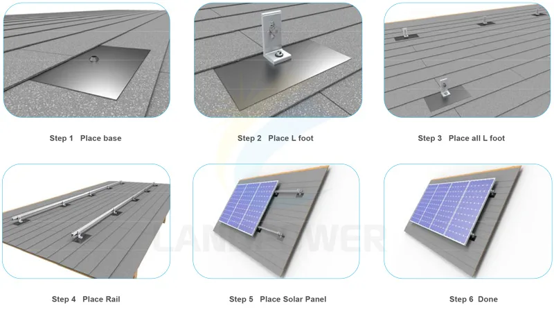
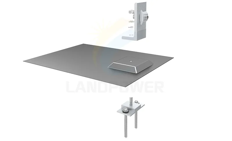
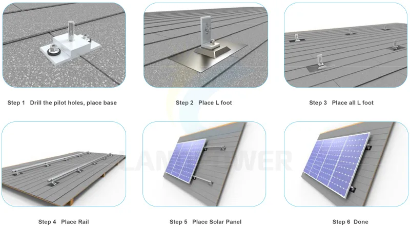
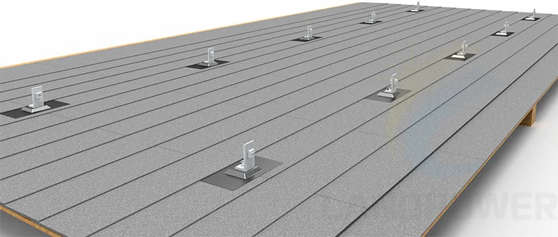
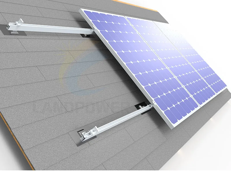
Current Source Specification Table
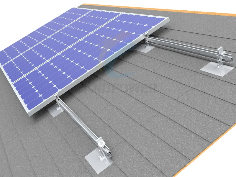
This table reproduces the current catalogue labels. Confirm the selected configuration, drawing revision, calculation basis and supporting documents before order release.
| Install site | Asphalt Shingle Roof |
|---|---|
| Tilt Angle | Flushed with the roof ( 10~60 deg ) |
| Building Height | 20 m |
| Max Wind Speed | <60m/s |
| Snow Load | <1.4KN/m2 |
| Standard | En 1090, AS/NZS 1170 and other international Standard |
| Material | Aluminum 6005-T5& Stainless steel A2( 304 ) |
| Color | Silver,Black or Customized |
| Anti-corrosive | A nodized aluminum & stainless steel ,EPDM |
| Warranty | 12 years warranty and twenty- year service life |
Current document status
Request the selected configuration and quantity schedule, interface drawings, product data sheet, material/finish and fastener records, module/clamp compatibility check, load/code basis where applicable, fixing/foundation or roof-interface details, installation/inspection instructions, packing list and signed commercial terms.
What the catalogue label does and does not confirm
Turn the named item into one controlled mounting scope
A product name cannot replace the drawing, calculation and interface information that controls a solar mounting supply.
Confirm the exact item
Identify the selected model, revision, dimensions, quantity, finish, accessories and any alternative parts; do not quote from a generic label alone.
Match the PV interface
Check the module frame and clamp zone, panel orientation, rail/table geometry, thermal movement, cable path, bonding route and service access against the final layout.
Define the building or ground interface
Roof construction, façade/balcony substrate, ballast zone, pile/foundation conditions or connection substrate determine the permitted fixing route and responsibilities.
Separate component from system scope
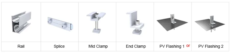
Rails, clamps, screws and drainage clips are components. They do not by themselves prove a complete mounting system, structural capacity or weather-management outcome.
RFQ inputs to collect
Use six evidence packages before releasing the mounting order
The required detail changes by route, but the selected supply must still connect to one verified project design.
Layout and module schedule
Provide the module model, frame thickness, clamp zones, orientation, row/table arrangement, roof or ground plan, clearances, shading constraints and final quantities.
Site, substrate and interfaces
Provide roof build-up or substrate information, survey levels, utilities, soil/foundation inputs where applicable, existing structure limits, waterproofing/drainage interfaces and access constraints.
Loads and local requirements
State site location, governing code and design wind, snow, rain, seismic and temperature conditions, plus deflection, ballast, pull-out, corrosion and permit requirements as applicable.
Material and corrosion control
Confirm aluminium/steel grade, coating or anodising, stainless/fastener grade, dissimilar-metal isolation, exposure category, cut-edge treatment and inspection records for the specified supply.
Installation and safety coordination
Define lifting, roof access, fall protection, torque/fastening controls, tolerances, bonding/earthing, cable containment, fire access, water route and handover inspection responsibilities.
Controlled documents and commercial scope
Request a configuration-specific BOM, drawings, calculation or design-responsibility statement where needed, certificates in scope, manual, packing, spares, exclusions, Incoterms, destination and signed warranty terms.
Approval boundaries
Do not convert marketing labels into engineering commitments
The final project documentation must support the installed configuration, site conditions and responsibility split.
Names such as adjustable or universal need limits
Confirm the actual adjustment range, supported module/frame range, layout restrictions, connection method and the evidence that applies to the selected version.
A ballast or fixing concept needs design verification
Roof capacity, uplift, sliding, drainage, membrane protection, pull-out, foundations and installation tolerances must be checked for the site; none can be inferred from the product name.
Water-management wording needs a full interface
Clips, gaps or named waterproofing routes do not establish drainage performance without the roof/building interface, falls, outlets, detailing, workmanship and maintenance plan.
Standards and certificates need exact scope
Ask for the applicable edition, issuing body, product/configuration coverage and project relevance. A generic declaration does not approve a different layout or site load case.
Continue the procurement review
Link the mounting selection to the project BOM
Use the project workflow and BOM guide to keep mechanical, electrical and document scope aligned.
Commercial solar procurement solution
Coordinate modules, mounting, electrical interfaces, site constraints and verification responsibilities in one project request.
Review project coordination →Solar BOM review guide
Use a controlled BOM to check rails, clamps, fasteners, structure, accessories, drawings, quantities, documents and exclusions before RFQ release.
Review the mounting BOM →Mounting configuration FAQ
Questions to resolve before selecting the supply
The answers must come from the chosen configuration and project evidence, not from a generic catalogue name.
Is Asphalt Shingle Roof Solar Mounting a complete mounting-system approval?
No. Confirm exactly which structural and accessory parts are included, then obtain the matching layout, interfaces, load/fixing evidence, installation scope and exclusions for the project.
Can the item be selected from module size alone?
No. Module frame and clamp-zone fit are only part of the review. The layout, substrate, loads, corrosion environment, drainage, access, cable and bonding interfaces also affect selection.
Do adjustable, ballast or waterproofing labels prove site performance?
No. Verify the applicable range and the full project design. Structural, roof/foundation, water-management and installation performance require configuration- and site-specific evidence.
What should the RFQ package contain?
Send the final module/layout schedule, site and substrate information, code/load basis, interface constraints, material/finish requirements, document scope, quantities, destination and required commercial terms.
Prepare a controlled asphalt shingle roof mount RFQ
Send the selected layout, module schedule, site/interface data, loads/code, materials/finish, drawings and document requirements, quantities and destination so the quoted scope can be verified.
Start with the product, application or project information you have. We can help identify the remaining configuration, document or delivery questions before a final quotation.
Verify the Mounting ScopeRelated Products
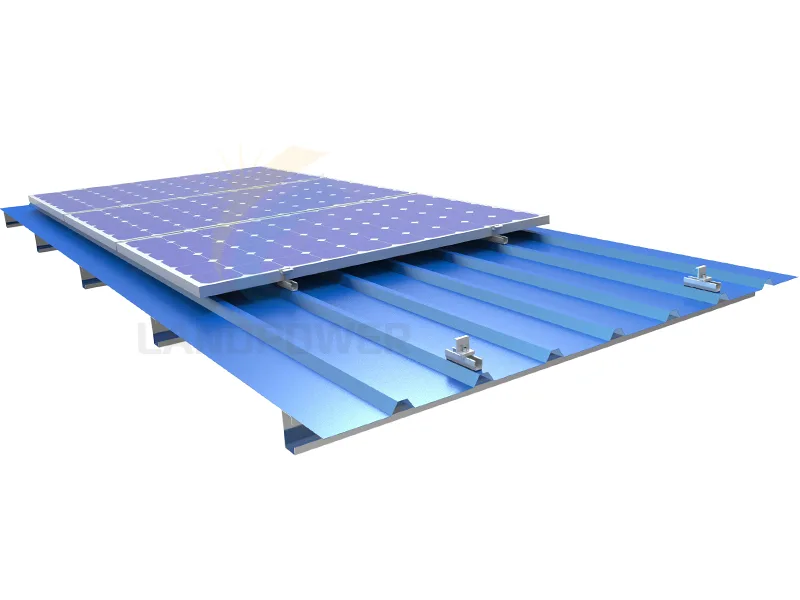 Pitched Metal Roof Mounting
U Rail Metal Roof Solar Mounting
U Rail is designed for Trapezoidal metal sheet roof or Corrugated sheet metal roof ,it is simple and easy solar roof mount solution for metal roofs.
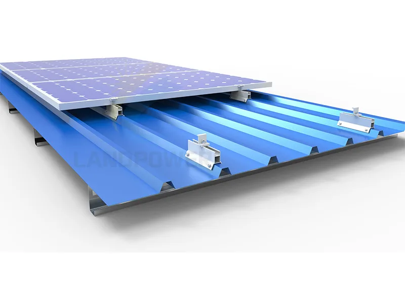 Pitched Metal Roof Mounting
Trapezoidal Roof Short Rail Mounting Systems
The Short Rail Mounting System is simple and quick mounting solution for placing solar panel on trapezoidal roof,just only Short Rail,Mid Clamp and End Clamp,quite easy for installation.
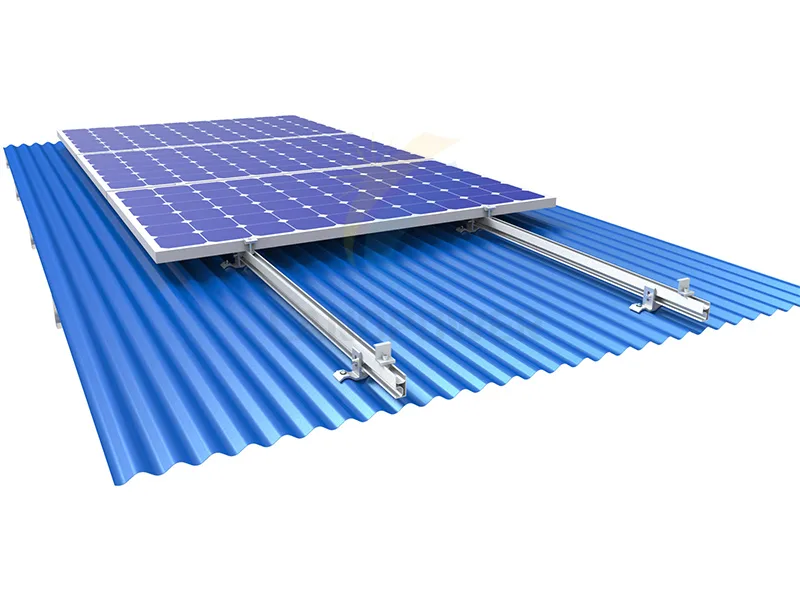 Pitched Metal Roof Mounting
Corrugated Roof LongRail Mounting Systems
The Corrugated Roof Mounting with roof clamp is specially design for corrugated metal roof sheet,coming with long rail,it is strong metal roof structure for corrugated metal roof.