
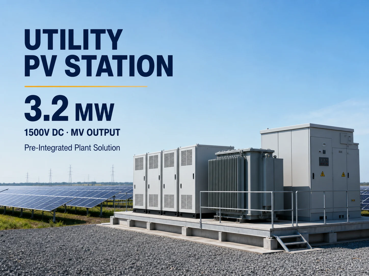
3.2MW Medium-Voltage Utility PV Station Project Platform
Current source identity: a neutral approximately 3.2 MW integrated-station concept; it is not a released manufacturer station model or fixed bill of materials.
This neutral project platform describes an approximately 3.2 MW AC station combining 1500 V string-inverter blocks, low-voltage collection, transformer equipment and a medium-voltage interface. It does not identify the number or model of inverters, exact LV/MV voltages, transformer rating/vector group/impedance, switchgear, auxiliary system, enclosure arrangement or grid-compliance package. The station must therefore be procured as a project-engineered BOM with studies, civil inputs, controls and acceptance requirements.
Current sourcing-configuration specifications
These values are preserved from the current internal product record. They define shortlist requirements, not a released manufacturer model; require a matching supplier datasheet before order.
PV Input & MPPT
| PV Input | 1500 V DC inverter blocks; final array sizing by EPC design |
|---|---|
| MPPT / Inputs | Multiple high-power string inverter MPPT blocks |
AC Output & Grid
| Rated AC Output | Approx. 3.2 MW AC |
|---|---|
| AC Output | Low-voltage inverter collection stepped up to medium voltage through integrated transformer equipment |
| Maximum Efficiency | System efficiency depends on selected inverters, transformer and auxiliary equipment |
Installation & Communication
| DC Voltage | 1500 V DC system; inverter operating window by selected block |
|---|---|
| Protection | Station protection, switchgear and environmental class configured for the project |
| Communication | Plant controller / SCADA integration and remote monitoring by project scope |
| Recommended Application | Utility-scale ground-mount PV plants requiring a pre-integrated inverter and MV transformation solution |
Current document status
Require the exact inverter/transformer/switchgear/auxiliary/PPC/SCADA BOM, SLDs and schematics, equipment datasheets, civil and transport drawings, grid-study models/reports, protection settings, FAT/SAT, commissioning, warranty and handover schedule.
Current station-platform evidence
Treat 3.2 MW as a planning class until the complete station BOM is frozen
Every electrical, physical and compliance interface is project-dependent.
Inverter block
The concept references multiple high-power 1500 V string-inverter blocks without count, model, rated AC voltage, MPPT/current schedule, redundancy or spare strategy.
Transformer and LV collection
LV collection and transformation are described without transformer MVA, ratio, vector group, impedance, tap range, efficiency/losses, temperature rise or cable/busbar rating.
MV and protection
The MV interface lacks voltage, switchgear topology, interrupting rating, relays, CT/VT, surge/lightning, metering, grounding, arc classification and utility protection scheme.
Physical and controls scope
Container/skid layout, HVAC, auxiliary transformer/UPS, fire detection, access, weight, lifting and PPC/SCADA protocols must be engineered for the project.
3.2 MW station RFQ checks
Six design packages required for a comparable station offer
Commercial comparison is meaningful only when all bidders price the same electrical and project boundary.
Design basis and SLD
Provide DC block size, inverter count, LV voltage, transformer/MV voltage, collection topology, POC, redundancy, auxiliary power and owner/EPC interfaces.
Transformer/switchgear
Define MVA, ratio/vector/impedance/taps/loss class, cooling, MV switchgear rating/topology, CT/VT/metering, relays, grounding and surge/lightning protection.
Grid studies
State load flow, short circuit, harmonics, reactive capability, LVRT/HVRT, frequency response, protection coordination, earthing and utility model-validation requirements.
PPC/SCADA and communications
Confirm protocols, signals, commands, time sync, weather station, revenue meter, cybersecurity, remote access, data ownership and communications-loss behavior.
Civil/logistics/site
Provide geotechnical/site climate, foundation loads, cable trenches, drainage, access, crane/transport limits, clearances, fire separation and environmental conditions.
Documents and acceptance
Request design review, type-test/certificates, FAT, delivery inspection, installation supervision, SAT, commissioning, grid tests, training, spares, warranty and as-builts.
Integrated-station boundaries
Pre-integrated does not mean pre-approved, site-ready or turnkey
The station still depends on the project network, civil design, utility process and contract scope.
Approximate MW is not a final export rating
Inverter active/apparent power, ambient derating, transformer rating/losses, auxiliaries, reactive requirement and utility export limit determine POC capacity.
MV interface cannot be generic
Voltage, fault level, switchgear, protection, metering, grounding and utility requirements must match the specific site and interconnection agreement.
Efficiency needs a system boundary
Inverter maximum efficiency does not represent station efficiency after transformer/LV/MV losses, auxiliary load, clipping, curtailment and downtime.
Pre-integration does not remove EPC responsibility
Foundations, cables, earthing, civil works, grid studies, utility approval, installation, testing and operational acceptance remain allocated project duties.
Continue the MV station review
Connect the integrated station to the full utility project scope
Use the procurement and BOM guides to align engineering, supply and acceptance boundaries.
Utility solar procurement solution
Coordinate inverter, MV station, modules, controls, studies, civil works, logistics and commissioning.
Review utility responsibilities →Project BOM review guide
Freeze equipment, accessories, interfaces, spares, documentation and exclusions before comparing station bids.
Review station BOM →3.2 MW MV station FAQ
Questions to close before issuing the utility RFQ
The answers belong in the project design basis and responsibility matrix.
Is this a fixed 3.2 MW manufacturer station model?
No. It is a neutral project platform. The final offer must identify every inverter, transformer, switchgear, auxiliary and control item and provide matching documents.
Does 3.2 MW equal export power at the POC?
Not automatically. Confirm active/apparent ratings, reactive requirements, derating, transformer and auxiliary losses, export limits and the utility-approved POC rating.
Which MV details are required?
Define voltage, fault level, transformer ratio/vector/impedance/taps, switchgear rating/topology, protection relays/settings, CT/VT/metering, grounding and utility interface.
What belongs in final acceptance?
Include document/as-built review, FAT/SAT, insulation and protection tests, transformer/switchgear checks, PPC/SCADA, grid-code witness tests, performance criteria, training and punch-list closure.
Prepare a project-engineered 3.2 MW MV station RFQ
Send the SLD/design basis, inverter block, LV/MV and utility data, study requirements, site/civil conditions, controls, logistics and acceptance matrix.
Start with the product, application or project information you have. We can help identify the remaining configuration, document or delivery questions before a final quotation.
Define the MV StationRelated Products
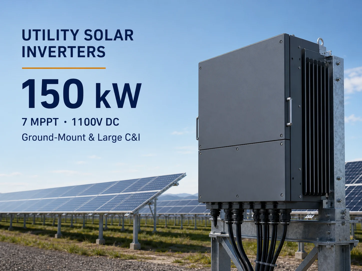
150kW Utility String Inverter
150 kW platform for ground-mount and large c&i pv plants on 1000/1100 v dc systems.

200kW / 215kVA 1500V Utility Multi-MPPT String Inverter
200 kW rated / 215 kVA maximum platform for 1500 v ground-mount pv plants and high-capacity tracker blocks.
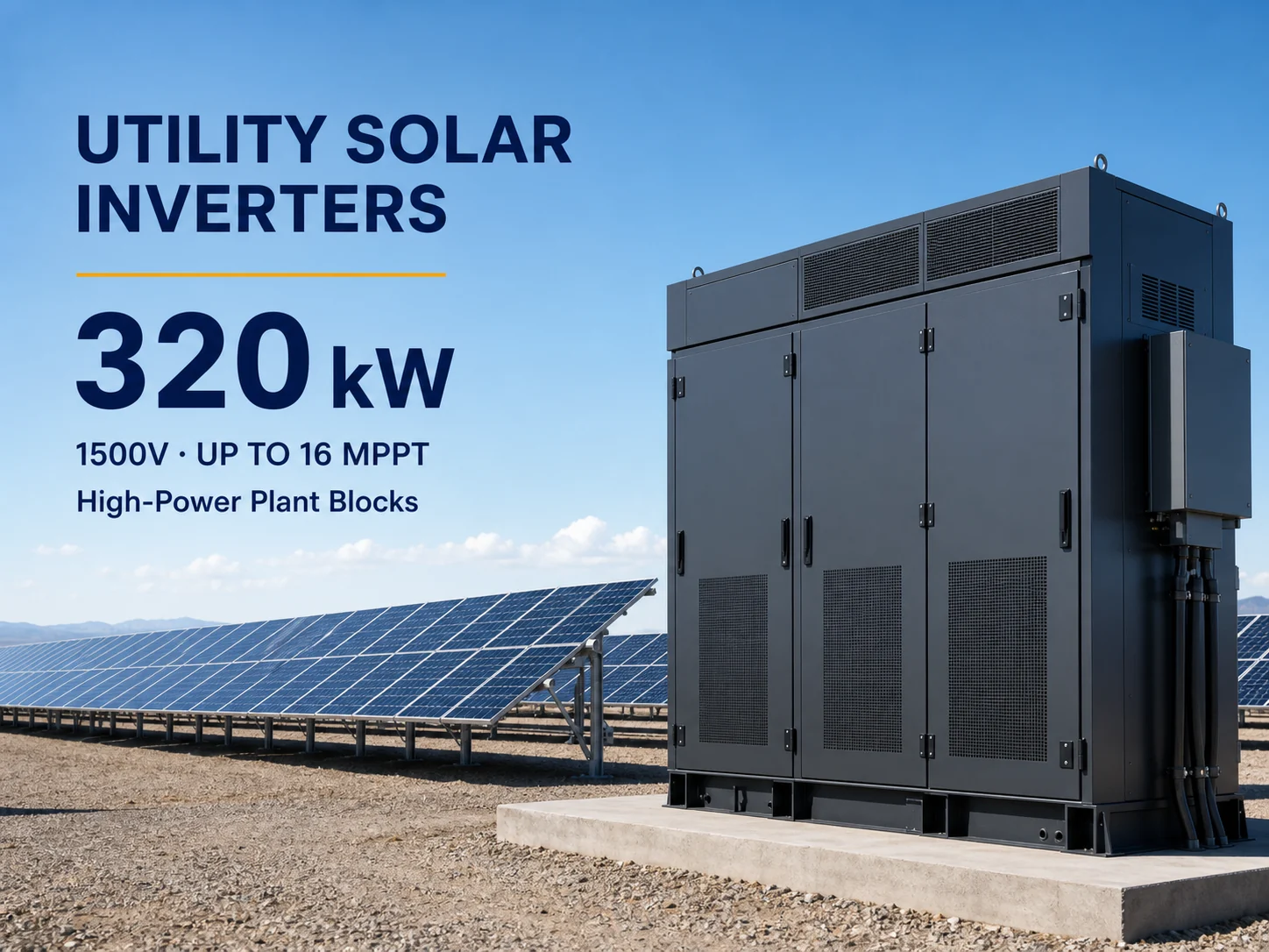
320kW 1500V Utility Multi-MPPT String Inverter
320 kW platform for large utility pv plants requiring high-power decentralized inverter blocks.