
How to expand a parallel 48V lithium battery bank
An empty rack bay proves there is room for another box. It does not prove the existing battery bank, busbars, inverter or BMS network can accept it.
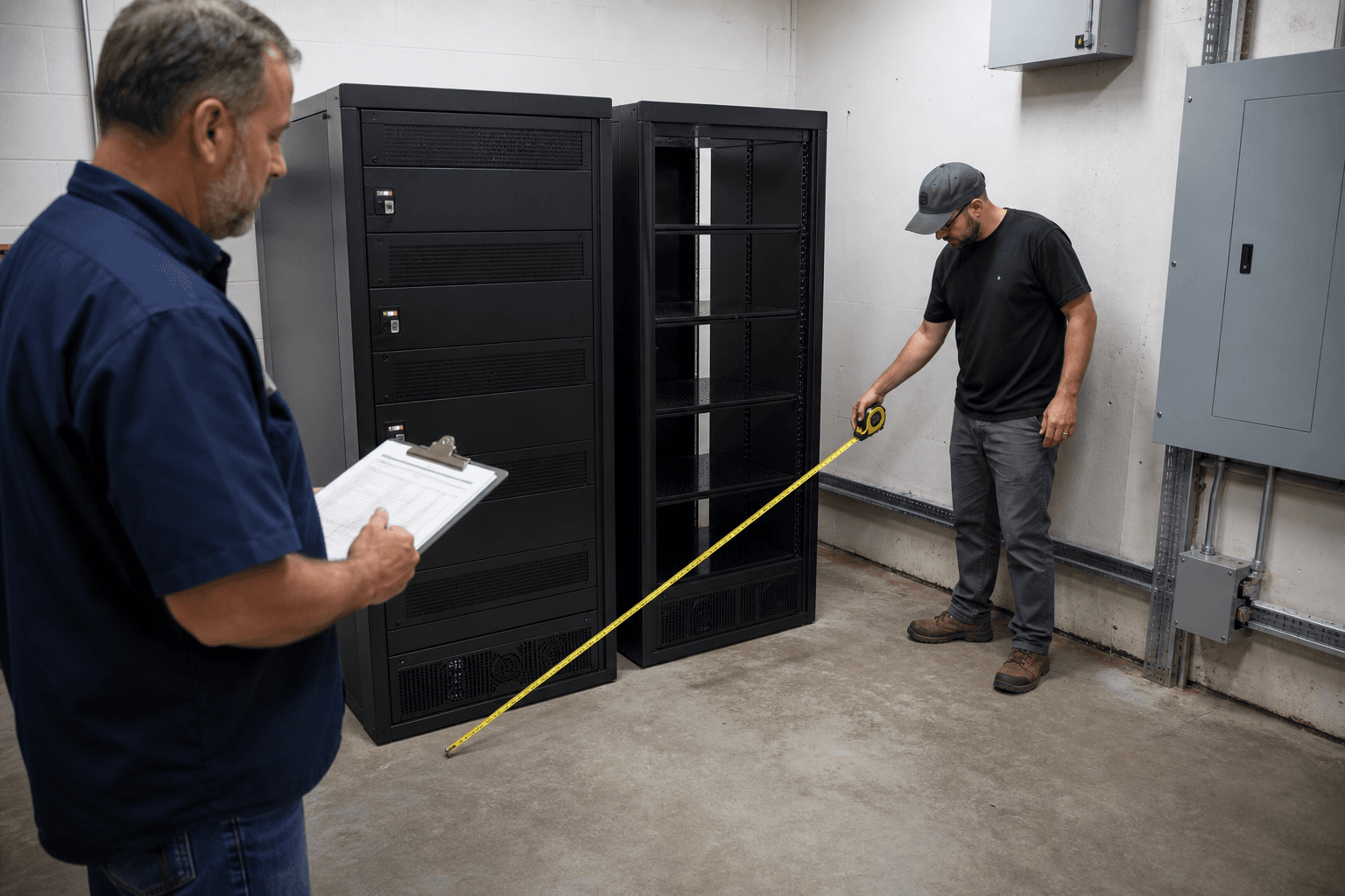
Battery-bank expansion often begins with a quick look at the cabinet: two spare bays, a little floor space, and an owner who wants longer backup. The physical gap is the easy part. Adding modules changes the bank's current paths, communication network, protection duty, weight, maintenance access and commissioning record.
The first question is whether the battery manufacturer permits the exact old and new modules to operate together. The second is whether the installed DC and communication architecture was designed for the larger bank. A shared 48V label cannot answer either one.
This guide is for planning an expansion and comparing supplier proposals. It does not provide wiring, protection sizing or live commissioning instructions. Those decisions require the exact manuals, a site review and the qualified parties responsible for local electrical and fire requirements. The photographs are illustrative editorial images rather than Rongkai project records.
Match the exact battery, not the voltage printed on the listing
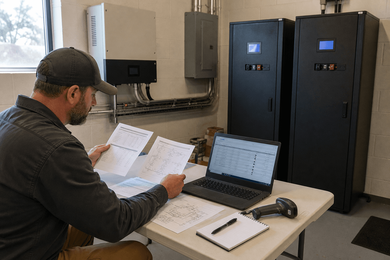
The label "48V lithium battery" covers many operating ranges, cell formats, BMS protocols, current limits, connectors and firmware families. Start with the complete model code, hardware revision, serial or production range and firmware for every installed module. Then obtain the manufacturer's current rule for adding modules to that bank.
The old modules have already accumulated calendar time, cycles and temperature exposure. Expansion may still be supported, but the manufacturer can require a health check, age limit, firmware update or an approved preparation process. If the exact model is no longer available, ask whether a named successor is approved in the same bank. A similar case, connector or nominal voltage is not substitution evidence.
- 1
Inventory the installed bank
Record exact models, revisions, firmware, module age, alarms and the existing inverter pairing.
- 2
Confirm expansion support
Obtain the manufacturer's rule for the proposed old/new combination and maximum module count.
- 3
Review the DC path
Check bank current, inverter terminals, busbars, disconnects, protection and the approved sharing topology.
- 4
Review the BMS network
Confirm addressing, leader roles, gateway capacity, termination and required firmware.
- 5
Survey the cabinet
Check weight, clearances, ventilation, cable space, isolation access and future module removal.
- 6
Commission and document
Verify every module, aggregate limits and controlled bank behaviour, then update the system record.
More modules add energy; the other limits do not all scale with them
Here is a teaching example. Four 5kWh modules provide 20kWh of nominal energy. Adding two compatible 5kWh modules would raise that nameplate total to 30kWh. A 10kW inverter remains a 10kW inverter, and the installed terminals, busbars, protection and backup circuits keep their own limits. The figures illustrate the distinction; they are not a design for a specific product.
Available bank current may increase when the approved battery architecture supports it, but it should not be calculated by blindly multiplying one module's rating. Discover's HELIOS documentation, for example, publishes bank-level limits and notes the effect of internal and external busbars. Those figures belong to that product family. Keep energy, battery current and inverter output as three separate lines in the proposal.
- Expansion item
- 4 × 5kWh to 6 × 5kWh
- What may change
- Nominal energy rises from 20kWh to 30kWh if the combination is approved.
- What does not change automatically
- A 10kW inverter does not become a 15kW inverter.
- Expansion item
- More parallel modules
- What may change
- Supported bank charge and discharge current may increase.
- What does not change automatically
- Terminal, busbar, protection and thermal ratings.
- Expansion item
- More stored energy
- What may change
- Runtime may increase for the same defined load.
- What does not change automatically
- Backup scope, surge capability or whole-site coverage.
| Expansion item | What may change | What does not change automatically |
|---|---|---|
| 4 × 5kWh to 6 × 5kWh | Nominal energy rises from 20kWh to 30kWh if the combination is approved. | A 10kW inverter does not become a 15kW inverter. |
| More parallel modules | Supported bank charge and discharge current may increase. | Terminal, busbar, protection and thermal ratings. |
| More stored energy | Runtime may increase for the same defined load. | Backup scope, surge capability or whole-site coverage. |
Use exact-model usable-energy and bank-limit data for a real proposal; the numbers above are deliberately simple teaching values.
Does adding more batteries increase inverter output power?
No. Additional batteries may increase stored energy and, in an approved design, the bank's available DC current. The inverter's AC rating, backup-output limits and the rest of the electrical system remain separate constraints.
Current sharing is decided by the complete path
Parallel batteries do not share current simply because their nameplates match. Every cable, termination, disconnect and busbar adds some resistance. If one module has a shorter or lower-resistance path, it can carry more of the charge and discharge current. Over time, the modules may show different SOC movement, temperature, alarms or ageing even though the bank total still looks normal.
Victron's Wiring Unlimited guide illustrates the underlying point clearly: current paths in a parallel bank should be arranged so their resistance is comparable. Busbars are one common architecture, but their presence alone does not prove equal sharing. The busbar rating, connection positions, module leads, lugs and installation quality still matter. The battery manufacturer's permitted topology takes priority.
An expansion review should therefore document the existing current path before a new cabinet is ordered. Ask the responsible designer to confirm the proposed bus and cable architecture against the bank current, fault level, product instructions and local requirements. This article deliberately stops short of cable sizes, fuse ratings and connection positions; those are design outputs, not safe universal tips.
- Existing single-line diagram and a current physical record of battery, disconnect, busbar and inverter connection points.
- Ratings and model details for the installed busbars, enclosures, disconnects and protection devices.
- Manufacturer-approved parallel topology and the design basis used to achieve comparable module current paths.
- Expected bank charge, continuous discharge and short-duration demand after expansion.
The communication network has to expand as well
A parallel lithium bank is both a power system and a data network. The BMS arrangement may need module addresses, a leader battery, a daisy-chain order, a terminator or a gateway that reports the aggregate limits to the inverter. Manufacturers set a maximum supported module count and may change that count by communication mode or gateway.
In a dual-inverter system, confirm how the battery data reaches both inverters and how the inverter leader/follower network is configured. The two communication paths have different jobs. Adding a battery can appear successful on the DC side while the new module remains absent from the aggregate SOC or current limit. A green indicator on the module is not enough; the approved service interface should show the complete expected bank.
Record the firmware and communication configuration before changing it. After expansion, save the new module list, addresses, gateway status and inverter battery page. If the product channel requires matched firmware, update planning should include the existing bank and the rollback or support route rather than treating the new module in isolation.
Can batteries from different brands or capacities share one parallel bank?
Do not assume so. Use a combination only when the responsible manufacturers explicitly support the exact models, revisions, communication method and operating limits together. Similar nominal voltage is not enough.
Use the cabinet survey to make future service easier
A rack can have spare units and still be a poor expansion site. Check support and total weight, ventilation, manufacturer clearances, access to disconnect handles, cable-entry space, door swing and the route for removing one module later. Local fire separation, egress and working-space rules also belong in the survey.
Look at the closed system from a service technician's position. Each module and isolation point should be identifiable from the records, with covered space for any larger busbar or communication hardware the manufacturer requires. Use the expansion to correct unclear labels and missing drawings, while keeping local enclosure, structural, electrical and fire work as a separately designed scope.
- Available rack units or floor area, total installed weight and the structural party responsible for approval.
- Manufacturer clearances, ventilation conditions, ambient temperature range and access aisle.
- Space for covered busbars, disconnects, protection, cable routes and communication accessories.
- Module identification, service access and the local party responsible for electrical, building and fire acceptance.
Commission the expanded bank as one system
Before the new modules arrive, capture a baseline from the existing bank: module list, SOC, available voltage and temperature data, alarm history, firmware and current operating limits. Resolve unexplained communication or current-sharing problems first. Adding capacity to a bank with an open fault usually makes the evidence harder to read.
The manufacturer-approved expansion procedure should define how the old and new modules are prepared, combined and recognised. Commissioning should then confirm that every expected module appears in the service interface, the inverter receives sensible aggregate limits, and no module consistently carries an abnormal share during a controlled charge and discharge test. The qualified team should also verify the installed protection, isolation, labels and thermal condition within the project scope.
Finish by updating the single-line diagram, module schedule, serial record, firmware record, settings backup and warranty file. Photograph the completed closed installation and keep the commissioning report with the original system documents. The next service visit should not have to reconstruct the bank from cabinet shapes.
- Baseline records and unresolved alarms from every installed battery before expansion.
- Approved expansion procedure and confirmation that the proposed old/new combination is supported.
- Updated configuration and controlled evidence showing all modules present and behaving within documented limits.
- Revised single-line drawing, model and serial schedule, settings record, warranty file and closed-installation photographs.
Is an external busbar always required for a parallel battery expansion?
No universal rule applies. The requirement depends on the battery's approved topology, module count, bank current, inverter connections and the ratings of the existing equipment. Follow the exact product documentation and the responsible designer's reviewed architecture.
Can a new battery be added to an older bank if the model number matches?
Possibly, but the model number is only the first check. Age, condition, hardware revision, firmware, present alarms and the manufacturer's expansion limits still need review before the modules are combined.
Related Articles
How do solar panels perform in clouds, heat, salt air and dust?
A panel's watt rating cannot describe every site. Learn what changes in cloudy, hot, coastal and dusty locations, and which details belong in a supply quote.
Read Article→
How to compare solar battery specifications before buying
Two batteries with the same kWh label can do different jobs. Here is how to read the numbers, check the missing details and compare like-for-like quotes.
Read Article→
Solar self-consumption and grid export: what equipment do you need?
For project buyers, installers and distributors: what to source as an equipment package, what to arrange locally, and what a useful supply quote should include.
Read Article→