
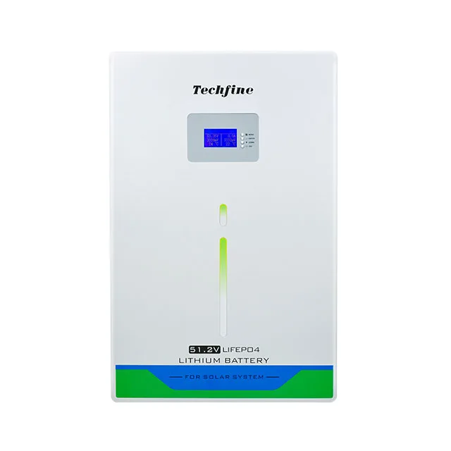
Techfine LB 25.6/51.2 V LiFePO4 battery: Verify Battery and System Scope
This page organizes the current source table for the Techfine LB 25.6/51.2 V LiFePO4 battery. 100/230/300 Ah members; table includes member-dependent current/energy routes. It does not convert a family energy value into usable system energy, runtime, inverter compatibility or a complete supplied system.
Current source route: LB 25.6/51.2 V LiFePO4 battery.
Current source parameter table
This table is preserved from the current source record. Read it with the identity, compatibility and document boundaries below; unresolved conflicts are not corrected by assumption.
| Models | LB100AH/51.2VTA | LB230AH/51.2V | LB300AH/51.2V | LB100AH/25.6V | LB230AH/25.6V | LB300AH/25.6V |
|---|---|---|---|---|---|---|
| Available Capacity | 5120WH | 11776WH | 14336WH | 2560WH | 5888WH | 8038WH |
| Electrical Specifications | ||||||
| Cell Chemistry | LiFePO4 | |||||
| Maximum Continuous Discharge Current | 100A | 100A\200A | 200A | 100A | 200A | 200A |
| Rated Voltage | 51.2V|DC | 25.6V|DC | ||||
| Voltage Range | 43.2V-58.4V|DC | 21.6V-29.2V|DC | ||||
| Maximum Output Power | 5120W | 5120W\10240W | 10240W | 2560W | 5120W | |
| Charging Parameters | ||||||
| Maximum Charging Voltage | 58.4V±0.2V|DC | 29.2±0.2V|DC | ||||
| Recommended Charging Voltage | 57.6V±0.2V|DC | 28.8±0.2V|DC | ||||
| Recommended Charging Current | 50A | 100A\115A | 140A | 50A | 115A | 157A |
| Charging Current Limitation Function | 10A | 10A\20A | 20A | 10A | 20A | |
| Power Consumption & Efficiency | ||||||
| Low Power Consumption | Working self-consumption ≤50mA, low-power mode ≤200uA | |||||
| Battery depth of discharge (DOD) | ≥95% | |||||
| Cycle life (standard charge/discharge at room temperature) | ≥5000 cycles | ≥5000 cycles | ≥5000 cycles | ≥5000 cycles | ≥5000 cycles | ≥5000 cycles |
| Protection Features | ||||||
| Long-delay Over-current Protection for Charge/Discharge | BMS100: Alarm >105A, Protection >110A/1s BMS200: Alarm >205A, Protection >210A/1s | |||||
| Instant Over-current Protection for Discharge | BMS100:≥150A/100ms BMS200:≥250A/100ms | |||||
| Over-voltage Protection Recovery | Discharge current >1A to recover (51.2V model: 59.2V, 25.6V model: 29.6V over-voltage point) | |||||
| Over-discharge Protection Recovery | Connect charger to activate (51.2V model: 43.2V, 25.6V model: 21.6V over-discharge point) | |||||
| Charge Over-current Protection Recovery | Discharge current >1A to recover | |||||
| Over-discharge current protection release | Released when charging current >1A | |||||
| Short-circuit protection function Present | automatically released during charging | |||||
| MOS high-temperature protection | MOSFET over-temperature protection | |||||
| Cell temperature protection | Protection for low cell temperature (-20°C) and high temperature (70°C) | |||||
| Ambient temperature alarm | Low-temperature protection -20°C; high-temperature protection 75°C | |||||
| Cell failure protection | Single-cell voltage difference >1V | |||||
| Display & Monitoring | ||||||
| Display | LED light strip indicator + LCD display | LCD display | ||||
| Communication & Expansion | ||||||
| Modules connection | 1-15 | |||||
| Communication | Standard RS232, RS485, CAN | |||||
| Environmental Ratings | ||||||
| Protection rating | IP21 | |||||
| Operating temperature range | Discharge: -10°C to +50°C; Charge: +0°C to +60°C | |||||
| Storage temperature | >1 month: 0–35°C; ≤1 month: -20–45°C | |||||
| Mechanical Specifications | ||||||
| Terminal type | M8 | |||||
| Depth × Width × Height (mm) | 720*480*170 | 785*510*293 | 755*490*253 | 532*347*170 | 475*420*255 | 476*496*255 |
| Weight (net weight, for reference)KG | 54.5 | 100 | 116 | 30 | 51 | 65 |
Current document status
Request the exact member datasheet, nameplate, BMS/communication schedule, current limits, wiring, supplied BOM, transport evidence and warranty before release.
Current source evidence
Keep energy, voltage and current on the same member
Battery selection requires the exact electrical member and the connected inverter/system design.
Member route
100/230/300 Ah members; table includes member-dependent current/energy routes
Energy and runtime
Nominal Wh does not establish usable energy or runtime; confirm discharge rate, cutoff, reserve, temperature and conversion losses.
BMS and compatibility
Voltage and LiFePO4 chemistry do not prove inverter/BMS communication, firmware, current limits or warranty compatibility.
System/BOM scope
For all-in-one routes, confirm whether battery, inverter, PV input, cables, protection, enclosure, commissioning and installation items are included.
Storage RFQ checks
Six checks before finalizing the battery or ESS
Define the selected member, electrical interfaces, operating duty and delivered scope.
Exact model
Request full model/suffix, revision, nameplate and table row.
Energy and power
Confirm nominal/usable energy, continuous/peak power/current, discharge limits, cutoff, reserve and temperature.
BMS and inverter
Confirm CAN/RS485 or other protocol, firmware, approved inverter list, settings and fault behavior.
PV and AC scope
For ESS, confirm PV/MPPT, AC input/output, grid/backup mode, loads, protection and transfer path.
Mechanical and safety
Confirm rack/case, terminals, cable, grounding, ventilation, transport, fire/site requirements and installation responsibilities.
Evidence and supply
Request manual, wiring, certificates for exact model/destination, BOM, warranty, packing, lead time and substitution controls.
Storage boundaries
A battery or all-in-one headline is not a complete project guarantee
Final capacity, compatibility, backup and grid behavior require the exact member and project-specific design.
Family-member boundary
Do not transfer energy, voltage, current, cycle, BMS or mechanical data across members.
Usable energy boundary
Nominal capacity differs from usable energy due to DoD, current, temperature, cutoff, losses and reserve.
Compatibility boundary
BMS pairing, firmware and inverter approvals require written exact-model evidence.
ESS scope boundary
All-in-one wording does not establish delivered PV, AC, battery, cables, protection, installation or grid-approval scope.
Continue the storage review
Prepare an evidence-based storage RFQ
Use existing sizing guidance to state the actual load, energy, power and system scope.
Storage FAQ
Questions to close before quotation
Exact member documents and project interfaces determine the final answer.
Which member applies to this LB 25.6/51.2 V LiFePO4 battery?
The current table route is 100/230/300 Ah members; table includes member-dependent current/energy routes. Request the exact selected code, nameplate and latest table before quotation.
Can nominal Wh be used as backup runtime?
No. Runtime requires usable DoD, load, power limits, conversion losses, cutoff, reserve, temperature and battery condition.
Will it work with any same-voltage inverter?
No. Confirm BMS protocol, firmware, current/power limits, settings and the exact-model compatibility approval.
What should the RFQ include?
Request exact datasheet/manual, BMS interface, wiring, current limits, certificates/transport files, BOM, warranty and delivery scope.
Prepare a verified LB 25.6/51.2 V LiFePO4 battery RFQ
Send load, energy/autonomy target, inverter or ESS topology, PV/AC route, destination and required documents.
Verify Storage ConfigurationRelated products
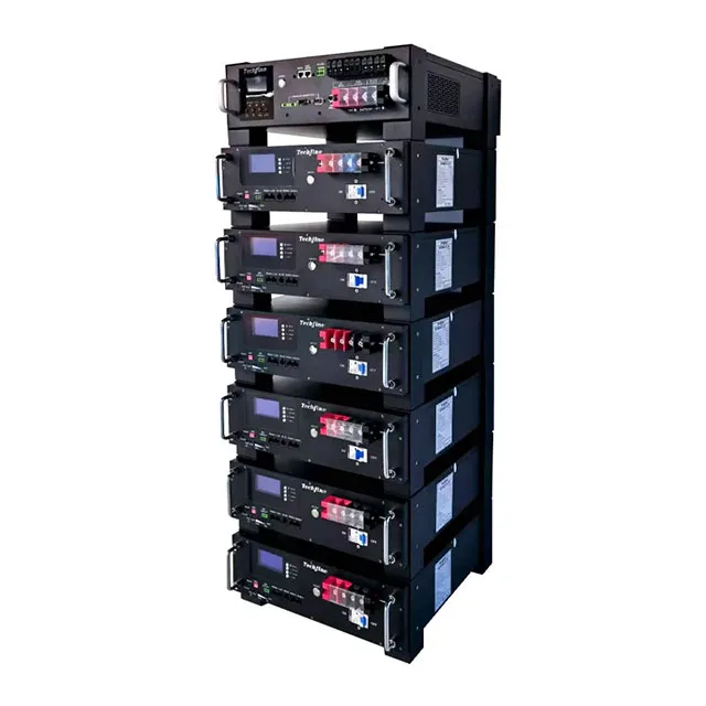 Storage Battery
LR-series | 100/230Ah 51.2V Rack-Mount Lithium storage Battery
Large capacity, high strength metal shell lithium iron phosphate battery, sufficient capacity
View Details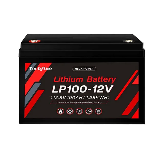 Storage Battery
LP-series | 50Ah–300Ah 12.8V lead acid replacement lithium solar storage battery
Large capacity, high-strength metal shell lithium iron phosphate battery, sufficient capacity
View Details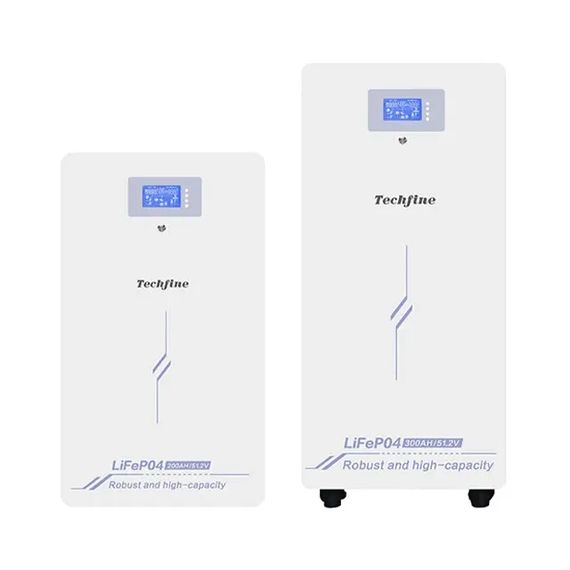 Storage Battery
LC-series | 100/230/300Ah 25.6/51.2V LiFePO4 solar storage battery
High-strength metal shell Lifepo4 battery with Large and sufficient capacity
View Details